LINC-CC
LINC-CV
LINC-CC
COR-TAP-Lite

BT-1-55v95w
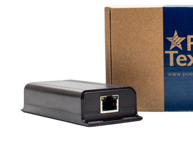
802.3bT (95 watt) PoE Injector
Welcome to the PoE Texas Manual for the BT-1-55v95w that cost effectively upgrades any non-PoE or PoE port to IEEE 802.3bt and 95 watts!
The purpose of the manual is to help you quickly and effectively navigate the installation and functions of your new Power Over Ethernet Midspan.
Our goal is to make our products as intuitive and simple to use as possible, so we value your feedback and questions directly to us at service@poetexas.com. Phone +1-512-479-0317.
Or you’re always welcome to leave questions or comments on our product pages: BT-1-55V95W
You can also download our Product Spec Sheet here.

What’s Inside

BT-1-55v60w
PARTS LIST:
- 1 X Midspan Injector with built in 6KV Surge Protection (designed for indoor use only)
- 1 X AC Power Cable
- 1 X Grounding Cable with Screw
Additional items you’ll need not included:
1 – Screws for mounting
2 – Patch cables to the switch and home run cables to the device
General Installation

A midspan like the BT-1-55v95w is a simple device to add on to a network port, and the purpose is to add or increase the PoE of that port without having to upgrade or pick a less optimal switch.
With this wall mounted device, simply mount it near the networking switch you’d like to pair it with. Then, using a short Ethernet patch cable from the switch’s data port to the LAN port on the PoE midspan. Then the POE port adjacent to the LAN port will now have that IEEE 802.3bt (95 watts) power budget and up to gigabit pass through data.
The BT-1-55v95w is also surge protected, so, while it cannot be mounted outdoor, you can connect it to outdoor devices with confidence. In order to make the surge protection fully functional, you will need to properly ground the connector on the side of the device.
Not sure what grounding is? Panduit has some great graphics around grounding.

CONFIGURATION
There is no configuration necessary with this device. Simply plug it in.
- The green LED indicates power on and drawing less than 30 watts. If the light turns blue, it indicates the port is drawing more than 30 watts of power.
- If the green light begins to blink at any time, it could indicate there is a short in the circuit or a compatibility issue.
STEPS TO TROUBLESHOOT:
1 – At the injector, disconnect the PoE port from your device. Use a PoE Tester to confirm the device is able to power on using a short jumper cable.
2 – At the other end of the network cable to your device, disconnect the device and use the PoE Tester to confirm it is able to negotiate PoE.
3 – Connect the PoE Tester to the end device to monitor power consumption.
If you’re able to power on the device with the PoE Tester inline, it’s likely a compatibility issue. Please contact us at service@poetexas.com to find you the right solution.
Technical Specifications
Product Specifications
| AC Plug Connector Type | C14 |
| Adapter length | 3 ft |
| Certifications | UL/CE/FCC |
| Data + PoE Ports | 1 |
| Data Ports | 1 |
| Data Rate | Gigabit |
| Dimensions | 6KV Model – 214mm x 134 mm x 41 mm |
| Display Type | LED – Green (802.3at) ; Blue (802.3bt) |
| IEC Protection Class | IP 40 |
| Input Frequency Range | 50/60 Hz |
| Input voltage | 100 – 240 VAC |
| Load Regulation | 6KV Surge Protection on Select model as indicated |
| Max Current | 1.72 Amps |
| Max Power for Kit | 95 Watts |
| Max Voltage | 55 volts |
| Max. Amps Per Port | 1.72 Amps |
| Mount Type | Wall |
| Operating Humidity | 20% to 80% |
| Operating Temperature Range | 0 – 40C |
| Output Voltage | 55 volts |
| PoE Method | IEEE 802.3af, IEEE 802.3at, IEEE 802.3bt |
| PoE Mode/Pinout | Mode A (-1,2 +3,6)/Mode B (+4,5 -7,8) |
If you find this learning center helpful, like and subscribe on your social channels to learn when we post new guides!
Denton Specifications
GBTS-28-24-M

GBTS-10-8-M
GBTS-10-8-M
Designer Toolkit Narrative

Concept Level Drawings
Generic CAD Drawings

PoE Lighting Bootcamp
PoE Lighting and Automation Bootcamp
This session includes the following:
1. Skills and lessons learned for PoE lighting installers
2. Wiring up your very first PoE lights
3. Programming a building automation system
Attendees will walk away with a basic skill set to design, install, and deploy a PoE lighting and automation system.
Watch the video training . . . or just download the presentation at the link below.
Explore our full line of PoE Lighting Products
Ready to Talk to Someone to Learn More?
Drop Us a Line to Schedule a One-on-One Consultation

GAT-USBC-PD-V3
GAT-USBC-PD-V3
PoE+ To USB-C 3.0 (Gigabit Data Rate)
Welcome to the PoE Texas Manual for the patent pending GAT-USBC-PD-V3 (designed for iPad, Microsoft Surface, and Samsung) that delivers wired Power and Gigabit Data for your USB Type C devices!
The purpose of the manual is to help you quickly and effectively navigate the installation and functions of your new Power Over Ethernet Converter.
Our goal is to make our products as intuitive and simple to use as possible, so we value your feedback and questions directly to us at service@poetexas.com. Phone +1-512-479-0317.
Or you’re always welcome to leave questions or comments on our product page: GAT-USBC-PD-V3
What’s Inside

PARTS LIST:
- 1 X POE+ Converter
GENERAL INSTALLATION
Your new PoE converter is designed to be simple to install and set up. It is small and light enough to leave “inline” with your network cable.
You may also choose to use four Keystone 616 mounting brackets to wall mount the device.
Otherwise, the GAT-USBC-PD-V3 fits many single gang wall boxes and all dual gang wall boxes.
Once it is in place, simply follow these steps in order:
1 – Plug the RJ-45 end into an IEEE 802.3at PoE (POE+) or 48-56 volt passive Power Sourcing Equipment (PSE) with a data source
2 – Ensure the device you’re connecting to is on and logged in
3 – Plug the USB-C connector into the device
The converter will automatically set up the network connection with your device and begin charging. To confirm that, go to the General settings tab or look for the <…> symbol next to Ethernet.


CONFIGURATION

Configuring Your Cisco Enterprise POE Switch for 2 Event PoE Classification
Yeah, I know that’s a mouthful. Here’s the simple translation. Cisco enterprise switches including the 9400 and 9300 models, which is a lot of them, come with a default setting that makes them less compatible PoE+ devices like the GAT-USBC-PD. You’ll know the setting isn’t right because our device won’t power on correctly, and your device won’t charge. How frustrating!
It’s a simple enough fix. You simply need to configure the ports that will power the GAT-USBC-PD to have 2 event classification. You can find the Cisco documentation on how to do that here: CONFIGURE MY SWITCH
Or here are the steps you take after you’ve logged into the terminal.
Switch> enable
Switch# configure terminal
Switch(config)# interface gigabitethernet2/0/1
Switch(config-if)# power inline port 2-event
Switch(config-if)# end
Microsoft Surface Go
There’s no configuration necessary for your Microsoft Surface products. You can simply use the connection as an Ethernet connection on the device.


iPad Pro Gen 3
Configuring Your iPad for Wired Data
There are a couple easy steps for configuring your iPad to get the best results when working with wired data.
First, we’re going to enable USB devices to allow charging even when the iPad is “off” or the screen is locked.
If you you don’t have the most up to date iOS software, take this time to update to iOS 12.2 or later. Otherwise, it will prevent any connected device from charging or communicating with it after the screen has been locked for an hour. Here’s how to fix that:
- Navigate to the Settings tab
- Select Face ID & Passcode
- Ensure the USB Accessories button is toggled to “On” meaning you see the green

You can still set up your iPad to not automatically lock on a timer. When the screen locks if you would like the screen always on.
- Go to the Settings icon on your iPad
- Select Display & Brightness
- Select Auto Lock
- Set the limit to Never
The splitter will auto-configure the IP settings to default as soon as you connect it up including Dynamic IP addressing.


- Navigate to General Settings, then you’ll see a symbol for the LAN <…>
- Select this and you’ll see the option for PoE Texas LAN, select it
You’ll see your IPV4 IP address information. If it shows “Automatic”, that means your getting a dynamically assigned IP address.
If you’d like to reconfigure the IP address, DNS, and HTTP Proxy settings, you can do that by selecting these options.
The most used option will be fixing your IP address by selecting the “Automatic” button.
For the other networks settings, we’d recommend talking to a service provider or give us a call: 512-479-0317 or service@poetexas.com.
Best Practices for iOS Updates
Despite Apple’s excellent reputation for ensuring backward compatibility with their iPads and iPhones, practical experience with a recent iOS update has revealed that even they can miss things which can temporarily lead to disruption of service for your device. If your device must be reliable 24/7, we recommend these following best practices:
- Go to Settings -> General -> Software Updates -> Automatic Updates
- Deselect “Install iPadOS Updates”
- Before choosing to install the next update, please check into our iOS Compatibility Table to check whether we have finished testing the performance of an new iPadOS version
iOS Compatibility Table
- Finally, to get emailed live updates on iOS compatibility, subscribe to our mailing list for iOS compatibility


Android (Samsung Tab and Google Pixel)
If you’re using a Samsung Tab A model year prior to 2019, you may experience some difficulties establishing the wired data connection. Please contact service@poetexas.com if you’re experiencing compatibility issues with your Samsung device.
Otherwise, simply confirm the data by looking for the Ethernet symbol on the upper right. No configuration necessary.

Technical Specifications
Product Specifications
| Adapters included | none |
| Connector Types | USB-C |
| Data Rate | (Input) 10/100/1000 Gigabit / (Output) 10/100/1000 Mbps |
| Data Standard | USB 3.0 (Output) |
| Input voltage | 48-56V |
| LEDs Per Port | Green (POE) / Yellow (USB-C) |
| Max Power for Kit | 25 Watts |
| Mount Type | Wall or Inline |
| Operating Humidity | -10 – 60C |
| Output Voltage | 5V,2.6A; 9V,1.78A; 12V,1.34A; 15V,1.37A; 20V,1.15A |
| PoE Method | IEEE 802.3at |
| PoE Standard | IEEE 802.3at |
| Weight | 3 oz. |
If you find this learning center helpful, like and subscribe on your social channels to learn when we post new guides!

PoE Lighting FAQ
Top Questions Answered by CTO, Joe Herbst, and CEO, Tyler Andrews
There are a lot of questiosn floating around online and in conversation about PoE Lighting and Automation. Joe and I will try to answer those questions in this blog. Don’t find the answer you need? You’re always welcome to reach out to us at:
or even speak to a real person at:
512-479-0317
Topics:
Market Information
Sales and Marketing
Design
Hardware
Installation
Integration
Market Information
What is the largets market, in terms of commercial real estate size, for PoE Lighting and Automation?
Answer:
Tyler: 90% of the real estate market are buildings and spaces less than 50,000 sq ft. Want to see where we get that infromation:
Has PoE lighting known to have been installed on any military installations?
Joe: We have one installation in a military SCIF facility (no internet no wireless allowed, Made in America)
Is there any information about residential use?
Joe: yes we have several residential sites – contact me for plans and drawings jherbst@poetexas.com. Or click on the link on the bottom of the page to schedule a meeting.
Do you have any use cases in hospital or clinical environments?
Joe: We have a assited living and Urgent care facilites that are PoE lighting control based.
Change is hard. How to leverage the need for PoE professionals for projects? Should I look for professionals with specific Certifications (besides electrician) for this job?
Answer:
Joe: Agreed. We have had great success with data installers and electricians vested in staying in touch with the evolution of tech. It is less about the historical skill set and more about their intellectual curiosity and willingness to learn. We train electricians at EJATCs and have had very positive results. We have also been successful teaching lighting and controls to datacom folks.
Sales and Marketing
What is the cost per sq ft savings that I can tell my client what percentage of savings they will see in real numbers?
Joe: We typically see 30% CAPEX (total installed) savings and 30-50% OPEX (operational expenses) savings.
Was the cost savings (60%) in copper based upon comparing a single run of #14/2 vs numerous runs (how many?) of 23awg UTP?
Joe: You typically need #14/5 to support dimming and be code compliant. Line, neutral, ground, Dim+ and Dim- Relative to AWG14 2 wire that we use that is a 60% savings in material.
Tyler: The other aspect of copper savings is in the reduction of electrical runs. To wire a traditional AC system, you have to run 14/2 from the breaker panel to all the lights in series and run to any light switches you’d like to control those lights. With PoE, those “connections” are done digitally. You can make the shortest, most efficient runs from the PoE switch to the fixtures or lights. Then you simply program any given light switch to control any desired fixture.
How do you sell a POE ligthing system to a client who has an existing normal lighting system? How do you convince the client to move over to the POE system?
Answer:
Joe: A conversion to PoE from an existing one is limited largely by sheetrock. If it is a substantial retrofit (down to studs) or new construction the pitch is easy. We sell rerofit kits that can get installed in the ceiling adjacent to the exisitng high voltage system and save money just on the efficiecies of LED over Fluerescent. See link for example
https://shop.poetexas.com/products/dent-lk-c4-b
Tyler: Converting to a PoE managed lighting system doesn’t necessarily mean the customer has to tear out all of their existing lighting. A good PoE lighting control system can also manage non-PoE lights while looking the same for your customer. See our lighting control panels below. So invite your customer to upgrade their current lights without tearing them out and adding PoE lighting as the project/needs arise.
Is the cost savings in copper based upon comparing a single run of #14/2 vs numerous runs (how many?) of 23awg UTP?
Answer:
Joe: You typically need #14/5 to support dimming and be code compliant. Line, neutral, ground, Dim+ and Dim- Relative to AWG14 2 wire that we use that is a 60% savings in material
Would PoE Lighting be suitiable for residental like houses and condos, for example how about a 2400 sq ft house?
Answer:
Joe: Yes it would be suitable.
What might a cost comparison be between a traditional lighting system and a SPOG setup for something like a 10,000 sqft office building? Would there be savings over traditional copper conductors? Are NFPA 101 requirements easily met?
Answer:
Joe: Please see our Midas case study. A PoE based lighting/controls system saves typically 30% on the capital side and 40-70% on the operational side. Primary savings come from: 100% less conduit (steel), 60% less copper wiring (18 AWG vs 12 AWG), and removal of AC to DC conversion at each light fixture.
It is difficult to provide a good ROI for PoE lighting for new construction, as well as retrofit. Is the PoE Consortium working on accurate cost estimate tools that include ALL the factors to build and maintain the system?
Answer:
Joe: You are absolutely correct this is hard. The biggest savings (conduit and copper savings) are hard to get a good number around. I have talked to many master electricians and the best numbers I have are 250ft of conduit per junction, but I have found too much varaince in that to give you a confident number. Other factors include the reduction in panels (since the power distribution is through PoE and there is a “circuit breaker” built into each port).
Design
What percentage of space increase in the Telecom rooms/racks are experienced by adding poe lighting?
Answer:
Joe: This is a tough one to answer beyond ‘it depends’….so follow my logic. Average building has ~ 0.1-1W lighting per ft^2. so assume 1W. Each port can feed 90W – so assume each port feeds 100ft^2 for easy math. Each switch then supports ~ 2400 ft^2 – round to 2500 for convenient math. Assume 1 full rack of equipment supports 10 24 port switches ~25k ft adds one rack of equipment. Be conservative and cut that in half for quoting
Tyler: We have a detailed package we share with designers to estimate the space, rack room, and cooling they’ll need for their PoE lighting system:
Who does the design to confirm proper light levels per code?
Answer:
Joe: We do design based on experience but if you want a formal lux map lighting layout we can connect you with a certified LC or engineer. We use the same IES files as a high voltage equivalent.
Tyler: We can provide a design with the IES file inputs that an architect and/or lighting designer can use to confirm the final design. If your customer doesn’t have access to someone for that and it’s a requirement for the job, we can call in partners who do this kind of thing every day for our customers.
Is Exit Lighting allowed to be PoE?
Answer:
Joe: Exit lights can be powered by 24VDC. We take a PoE 24v splitter and attach all the exit sign to one of the PoE switches that has EM backup AND use exit signs that have 90 minute battery backups
Tyler: We have multiple options for achieving PoE enabled exit lighting including a range of fixtures and methods. We customize the solution to fit the job.
How many lights can be supported from one 90 watt switch port?
Answer:
Joe: Typical examples are: 4 20W 2×2 panels, 3 25W 2×2 panels, 2 40W panels but no reason you can not do 10 8W fixtures or 12 5W fixtures.
Can this system also handle security, ie instead of cameras?
Answer:
Joe: This system can incorporate cameras into the control of lighting or messaging. So a camera can let us know motion was detected. We then connect that to actions such as “turn on the lights and if it is after 10pm text the security guard” or the camera tells up 5 people are in a conference room – we can send a message to the HVAC to tun on ventilation.
What is the recomended CAT cable?
Answer:
Joe: cat6 or better ; cat5e is also ok
Tyler: The key is selecting a CAT rated cable with 23 awg or less so you can handle the power load. Many CAT 6 cables are already 23 awg, and some manufacturers like Superior Essex and Berk-tek make a CAT 5e cable with 23 awg for PoE lighting applications.
How do you handle emergency lighting? What about potential switch failure? How do you handle emergency lighting with UL924 or UL1008?
Joe: We design two network stacks – one UPS backed or connected to EM power, the other utility power. EM fixtures can then be connected to the EM network switches and have ability to go to 100% on utility power loss using a UL924 transfer switch – contact me for drawings.
Tyler: On the switch failure question, the best contractors we know intentially spread the lighting across multiple switches, basically ensuring that no one area would be totally affected by a single switch failure. It provides overall system redundancy.
In a typical PoE installation, are the back-of-house components typically housed in telecom, or electrical rooms? Who maintains and administers, the electrical dept. or IT dept.?
Joe: I have seen them housed in either or both closets. Who maintains it is more about the politics of the organization and who holds the purse strings but ultimately we can support facility managers up to CIO’s.
Tyler: We have started encouraging building owners and facility managers to own their own PoE switches separate from the IT infrastructure. It’s called OT infrastructure. Facility managers need control of their own network hardware, and IT managers are often happy to stay out of it.
Will you homerun to each driver and patch cord to each LED?
Joe: PoE Switch to driver (LINC) via cat6, then AWG18-2 to each fixture up to 4 fixtures. LINC usually sits in cable tray close to fixtures. For small facilities, put all the LINC nodes in the closet and just run 18-2 from closet to each of the fixtures.
Is there a sigle line drawing showing how the system is wired?
Joe: yes – contact me jherbst@poetexas.com
Tyler: You can find wiring drawings in our designer toolkit.
What is the function of PoE in the SPOG? Do the systems to be controlled or integrated have to be PoE energized?
Answer:
Joe: PoE is not a requirement. But the SPOG has to host a browser (to quickly adapt to changing information) and thus must have an ethernet or wifi connection for the data. PoE represents the dual benefit of data+power so if you have to pull wires to power a pane of glass why not bring data into the same cable and remove a lot of cost and complexity. The PoE w/r/t the system is just a backbone. Any legacy or future system can be incorporated into the data+power PoE paradigm but the “E” in PoE is where all devices have optimal connectivity given its prolific, trusted infrastructure. The “P” part essentially gets rid of wall warts and AC to DC conversion losses.
Are there provisions for ACL-type role assignment? I have diverse users with tiered levels of needed access (think: secretary, building admin, maintenance).
Answer:
Joe: Using the kiosk mode you can lock it to a specific “room” which only has certain buttons. But there is no difference between a “room” and a “person” or a “role” in our paradigm. So each POG (wallstation) can be locked to a specific page and you specify what is on that page. No limit to the number of pages. The Admin has access to all the pages and the setup for each. So yes we can support as many roles/people/rooms as you want and then have one POG locked to that web page.
Does the POE powered lighting emergency specification/code match the same duration and as 277VAC emergency lighting uptime?
Answer:
Joe: The PoE emergency lighting can be setup to provide whatever duration you want. Code stipulates 90 minutes but based on the number of fixtures and the size of the UPS you can exceed this. We don’t have the traditional restrictions of a fixed circuit wiring so you can add/move/remove any fixture from the emergency response system.
Is power dissipation in cable is an issue when using PoE?
Answer:
Joe: The power dissipation is incorporated into the PoE specification so you don’t need to worry about it. The maximum loss on a 100m (328ft) cat 6 is 18W so a 90W source would deliver 72W worst case. In most installations this power loss is typically less than 5W.
Is intelligent passive cabling preferable to monitor ports apart from active network?
Answer:
Joe: PoE is backward compliant with passive switches – it just offers the option to add power if the device (PD) on the other side negotiates to need some. If there is no negotiation then there is no power put on the line.
What is the future of SPOG based on NFPA 70 Article 726 "Class 4 Fault-Managed Power Systems"?
Answer:
Joe: The two are not directly coupled other than being new technology. Class 4 FMP is all about safety. Touch the line, cut the line, fault it in any way the source upstream cuts the power. To the degree the SPOG is not downstream from that power cut it can notify you of such events. So a SPOG can be on a seperate power distribution system but monitor fault events elsewhere in the network and give immediate notification of the event in whatever form you want (email, text, light turning red, web button flashing etc).
Does each device need a separate license to be purchased? For the end user, as one tenant may have multiple user's at different rooms?
Answer:
Joe: No recuring fees – comes with lifetime license. Each SPOG can be limited to only display the elements in that room and not have visibility to other rooms.
Should we use separate networks or VLANs for all PoE devices?
Answer:
Joe: Lighting should ideally be a separate network but a separate VLAN at a minimum. Lighting is latency sensitive – press a button and you must respond in less than half a second. Having a network that has media streaming interfere with that is undesirable.
Hardware
What is the controller with the USB stick? What does it do? Who makes it?
Answer:
Joe: We make the controller – it is called a CORTAP. It is the “air traffic controller” for the building
Tyler:
General costs of a high power switch?
Joe: Our 24 port 2.1kW all ports 90W capable + 3000W dual hot .swappable rectifier sells for $1800.
Tyler:
What is a rectifier? Who makes it?
Answer:
Joe: The rectifier converts AC (120VAC to DC (53VDC) up to 3000W
Tyler: We have it made for us by a trusted partner.
How compatible are the lighting systems/software with BMS platforms like Niagara? Can data be shared to allow for lighting occupancy sensors to also control mechanical systems?
Answer:
Joe: The gateway can connect to a Niagra system and share information such as occupancy status.
Would this have its own application to control the system or could it be integrated into a BMS system such as Jonhson Controls Metasys?
Answer:
Joe: It has its own management software, connects to conventional wallswitches and occupancy sensors. It can also connect to other systems like JC through relay contact closures or through our REST API interface.
Most heat load happens at the fixture, not at the data switch, correct?
Joe: AC to DC conversion is not efficient and one of the benefits of PoE is you remove that heat loss at each fixture.
Tyler: Most of the heat loss is in the rectifier followed by the PoE switch. The heat losses at the fixture are minimal.
Where are we getting "fancy" fixtures? Seems like we only see flat panels & strips.
Joe: We do fancy fixtures as well as plain jane light bulbs and grid lighting. We support almost any type of fixture.
Tyler: If it’s LED, you can likely make it PoE powered. If you’d like ideas on cool light fixtures already PoE approved, we recommend visiting our friends at LED Industries who make some really cool fixtures.
Where do I find cut sheets for all of this?
Joe: Contact me jherbst@poetexas.com
Tyler: We have a full package we share on all of our products.
Do you know of a rack mounted UPS brand/model that is UL rated for emergency lighting?
Joe: We resell a UL924 EM battery backup system
Tyler: Unfortunately, no one yet has a rack mounted UPS system with a UL 924 rating. We have to go off rack for now. But we’re working hard to make that a reality.
Can four 20W fixtures on a single 90W port be controlled individually or must a home run to each fixture be required to control separately?
Joe: Each can be controlled individually
Tyler: The LINC has 4x outputs, so you can control each output independently if you’d like.
Do the fixtures come with a POE driver or are they field installed?
Joe: The LINC is the PoE driver and you can retrofit 98% of the lights today by bypassing the AC driver and connecting the LINC output to the LED +/LED- of the fixture.
Tyler: Some brands will pre-install the driver into a light fixture. Our experience has been, though, that no matter what fixture we install a driver into, it will not be the fixture the architect, designer, or owner wants. It also reduces the efficiency in field wiring because then every fixture needs a homerun CAT cable. So, we opted to allow for field wiring.
How easy is it to swap out the main displays on wallstations should it be damaged, and what (if any) set up would be required to return the system to full functionality?
Answer:
Joe: If you had a spare wallstation it is literally plug in the new one and it auto updates. That is the beauty of making it a web page and putting it into kiosk mode. It has one job and it does that one job in a “plug and play” way.
Do you provide 90W PoE switches?
Answer:
Joe: We provide one that does 90W per port and we have a 24 port version and an 8 port version (so 2.1kW and 720W respectively) Cisco, transition networks also offer switches but may not support all 24 ports at 90W.
Installation
May have missed it, however for the Project did you utilize licensed electricians to complete the install or structured cabling technicians? If you used the cabling techs, did they have a license or certified in structured cabling, and what license or certificate did they have?
Answer:
Joe: No electricians needed! Anyone can install it but structured cabling folks with experience with cat cable are ideal. No certification needed because it is all class 2 power. But we recommend and refer people with certifications so they can install and quote with minimal challenges or oversights.
Tyler:
I've seen systems in the past in which you effectivly have to chop off one end of the Category cable to terminate onto a Phoenix connector or some other type of connector. Is all of this now actually just RJ45 plug and play?
Answer:
Joe: The cat6 is IEEE802.3bt compliant – it is not just a RJ45 connection to 8 wires. It is standard compliant. The LINC driver has PoE input and 18AWG-2 wires out to the LED and performs the driver function of the LED.
Tyler: It depends on the manufacturer, however, we have made all of our devices to accept RJ-45 connectors where they connect using the CAT cable.
Do you run into cases where the CAT cable for the lighting has to be installed in conduit for physical security or protection?
Joe: No. Outside of Cook County IL a cable tray or JHOOK is acceptable.
Tyler: While it’s always best to check the local code standards – by the way, this can easily be done with a quick visit to the city to simply ask what you need to know – we’ve found 99% of municipalities are excited to see PoE lighting. However, you and the owner may decide that in certain key areas potentially exposed to weather or vandalism do require conduit.
Can contractors do commissionings and field functional changes?
Joe: yes – if you can navigate a web page – I will train anyone interested.
Tyler: Yes, Joe is serious. He has a one hour online tutorial you can do through Zoom which will show you all the major steps in wiring, commissioning, and programming a system. Click in the link at the bottom of the page to schedule your own training.
Is the Best Practice to restrict length of run to 100m due to voltage drop or balancing properly spaced Telecom rooms?
Joe: yes cat6 < 100m to conform to standard.
Tyler: I would extend that answer to “it depends”. Our 8 port PoE++ switches accept Fiber data and are designed to be installed in enclosed spaces like ceilings. So you can either choose to have telecom rooms spaced around the facility or you can choose a distributed network system where switches are mounted in the ceilings. The Sinclair Marriot has a distributed network system like that. It’s a design preference.
Does each switch and light fixture require a home run cable?
Tyler: No. Most manufacturers, including us, allow you to control multiple fixtures from one node. For example, in our case, the LINC has four output channels. You can control anywhere from one to ten fixtures depending on type and functionality.
Can this system be installed by Data Technicians and Electricians? All copper cabling, correct?
Answer:
Joe: Anyone can install it. Since it is class 2 you do not need a license to install it. AWG 18-2 and cat6 are all you need.
What is the typical rack space PoE light consumes? Maybe in a patch panels/sq ft?
Answer:
Joe: ROUGH estimates: 0.5W/SF each 2U rack space hosts 2.1kW of power or ~ 4k SF.
Integration
How many SPOG interfaces can you have on the system and can you limit the level of access?
Answer:
Joe: We can restrict access and no limit to the number of interfaces. We believe in a layered UI approach allowing you to delve down the “rabbit hole” as far as you want.
Is the SPOG similar or does it interface with building automation systems (BAS)?
Answer:
Joe: The SPOG can take information from the BAS and be a UIX point for that. BAS systems vary wildly so I have yet to see a consistant interface that crosses manufacturers and they are typically tied to a proprietary agenda (ex Lutron, Honeywell, JCI etc).
Can you list some of the more prevalent open standards you integrate around? BACnet? MODBUS? MQTT/REST/JSON?
Answer:
Joe: REST/JSON are our basis of design. We have done integration with BACNET via IP calls and relay closures. MQTT is on the Q1 roadmap. MODBUS is a VERY old standard. We could interface to it if the business case made sense but when you have 1Gbs available on PoE it is hard to go back to buad rates that have k in them 🙂 We also interface to DALI (Also slow), DMX, enocean, zigbee, BLE and wifi.
What integrations are common with security/access control systems? What are on the horizon?
Answer:
Joe: A common integration is FOB, keypad or App (bluetooth) entry via a reciever. The acesss event is matched against a database and the point of access (ie door number). If an affirmative match is found then the door is opened via a mag lock, door strike or bar for some time (ex 10 seconds) and then the lock is reapplied. The lock can also have a manual “request button” that can connect with a human (local or remote) and a camera to then support manual opening of the door (local or remote). These are all available today. We can also do other actions like setting lights to a specific level in a specific room or set the temp on the thermostat to a desired level (ex weekend entry).
What is a common open standard for the SPOG?
Answer:
Joe: REST API – it is the standard that runs on every web page on the planet.
Is the SPOG just software operating a typical wall screen?
Answer:
Joe: SPOG in our paradim is a touch interactive web page put into kiosk mode (so single purpose). The content for the web page is served up by our cortap server who is responsible for the controls and data collection of all the components for the building. Part of this is integration with other systems, part of this is direct control over devices but all tied together in one UI.
Is there a specific software that is easier to integrate or can any access control system be integrated to it?
Answer:
Joe: Any access control system can be integrated into our system that hosts a dry contact relay closure. More sophisticated ones we can connect to through an API and a commmunication medium (wired or wireless) Our PoE LINC devices control 12/24/36/48 V devices including door locks and can be tied to any stimulus event (ex relay closure or REST API call).
Ready to Learn More?
Click here to schedule some quality one-on-one time with our CTO, Joe

AF-USBC-PD

AF-USBC-PD – The PoE (12 watt) Converter for Power Delivery USB-C Devices including tablets
Welcome to the PoE Texas Manual for the patent pending AF-USBC-PD designed for USB-C power delivery devices including Apple iPad Mini and Air, Samsung Tab, and Amazon Fire that gives you wired Power and Data for your compatible USB Type C devices!
The purpose of the manual is to help you quickly and effectively navigate the installation and functions of your new Power Over Ethernet Converter.
Our goal is to make our products as intuitive and simple to use as possible, so we value your feedback and questions directly to us at service@poetexas.com. Phone +1-512-479-0317.
Or you’re always welcome to leave questions or comments on our product page: AF-USBC-PD
What’s Inside
")
PARTS LIST:
- 1 X POE Converter
Tested compatible with iPad Mini, iPad Air, iPad Pro 11″, Samsung Tab S7 Lite, Samsung Tab A8, Lenovo M10+, and more
Please contact us at success@poetexas.com if you’d like to confirm your compatibility
GENERAL INSTALLATION
Your new PoE converter is designed to be simple to install and set up. It is small and light enough to leave “inline” with your network cable and designed to fit inside a US dual gang wall box or simply inside the wall.
Once it is in place, simply follow these steps in order:
1 – Plug the RJ-45 end into an IEEE 802.3af PoE (POE) or 48-56 volt passive Power Sourcing Equipment (PSE) with a data source
2 – Ensure the device you’re connecting to is on and logged in
3 – Plug the USB-C connector into the device using the port you prefer


CONFIGURATION
IEEE 802.3af PoE – No Configuration Necessary
As a PoE device – not PoE+ or PoE++ – this device is compatible with ALL PoE switches and does not require any configuration on the switch side.
iPad Pro and 10th Gen
Configuring Your iPad for Wired Data
There are a couple easy steps for configuring your iPad to get the best results when working with wired data.
First, we’re going to enable USB devices to allow charging even when the iPad is “off” or the screen is locked.
If you you don’t have the most up to date iOS software, take this time to update to iOS 12.2 or later. Otherwise, it will prevent any connected device from charging or communicating with it after the screen has been locked for an hour. Here’s how to fix that:
- Navigate to the Settings tab
- Select Face ID & Passcode
- Ensure the USB Accessories button is toggled to “On” meaning you see the green
You can still set up your iPad to not automatically lock on a timer. When the screen locks if you would like the screen always on.
- Go to the Settings icon on your iPad
- Select Display & Brightness
- Select Auto Lock
- Set the limit to Never
The splitter will auto-configure the IP settings to default as soon as you connect it up including Dynamic IP addressing.
- Navigate to General Settings, then you’ll see a symbol for the LAN <…>
- Select this and you’ll see the option for PoE Texas LAN, select it
You’ll see your IPV4 IP address information. If it shows “Automatic”, that means your getting a dynamically assigned IP address.
If you’d like to reconfigure the IP address, DNS, and HTTP Proxy settings, you can do that by selecting these options.
The most used option will be fixing your IP address by selecting the “Automatic” button.
For the other networks settings, we’d recommend talking to a service provider or give us a call: 512-479-0317 or service@poetexas.com.
Best Practices for iOS Updates
Despite Apple’s excellent reputation for ensuring backward compatibility with their iPads and iPhones, practical experience with a recent iOS update has revealed that even they can miss things which can temporarily lead to disruption of service for your device. If your device must be reliable 24/7, we recommend these following best practices:
- Go to Settings -> General -> Software Updates -> Automatic Updates
- Deselect “Install iPadOS Updates”
- Before choosing to install the next update, please check into our iOS Compatibility Table to check whether we have finished testing the performance of an new iPadOS version
iOS Compatibility Table
- Finally, to get emailed live updates on iOS compatibility, subscribe to our mailing list for iOS compatibility
Android (Samsung Tab and Google Pixel)
If you’re using a Samsung Tab A model year after 2019, you may experience some difficulties establishing the wired data connection. Please contact service@poetexas.com if you’re experiencing compatibility issues with your Samsung device.
Otherwise, simply confirm the data by looking for the Ethernet symbol on the upper right. No configuration necessary.
Technical Specifications
Product Specifications
| Adapter length | 3 inches |
| Cable connector length | 36 inches |
| Cable connectors | USB-C Male – Integrated |
| Certifications | CE, RoHS |
| Data Rate | 10/100 Mbps |
| Dimensions | 3x1x1.5 in. |
| Input voltage | 44 to 56 volts |
| LED Indicator | Green – PoE; Yellow – Activity |
| Max Voltage | 5 volts |
| Max. Amps Per Port | 2 amp (PD Profile) |
| Operating Humidity | 5% to 90% |
| Operating Temperature Range | -10 – 60C |
| PoE Mode/Pinout | Mode A (-1,2 +3,6)/Mode B (+4,5 -7,8) |
If you find this learning center helpful, like and subscribe on your social channels to learn when we post new guides!

DENT-LK-C
DENT-LK-C Installation and Configuration Manual
Welcome to the PoE Texas Manual for the DENT-LK-C line of products!
The purpose of the manual is to help you quickly and effectively install and configure your new DENT-LK-C kit.
Our goal is to make our products as intuitive and simple to use as possible, so we value your feedback and questions directly to us at service@poetexas.com. Phone +1-512-479-0317.
Or you’re always welcome to leave questions or comments on our product pages: DENT-LK-C.

What’s Inside

PARTS LIST: DENT-LK-C2-A
- Qty 1 DENT-LINC-CC
- Qty 1 GPOE-1AB-56V60W
- Qty 1 DENT-WS-S4
- Qty 2 LTG-FP-2-2-4K
PARTS LIST: DENT-LK-C2-B
-
- Qty 1 DENT-LINC-CC
- Qty 1 GPOE-1AB-56V60W
- Qty 1 DENT-WS-S4
- Qty 2 DWN-4-RDG-WH


PARTS LIST: DENT-LK-C4-A
-
- Qty 1 DENT-LINC-CC
- Qty 1 GPOE-1AB-56V60W
- Qty 1 DENT-WS-S4
- Qty 2 LTG-FP-2-2-4K
- Qty 2 DWN-4-RDG-WH
PARTS LIST: DENT-LK-C4-B
-
- Qty 1 DENT-LINC-CC
- Qty 1 GPOE-1AB-56V60W
- Qty 1 DENT-WS-S4
- Qty 4 LTG-FP-2-2-4K

Accessories and Tools
Not Included in Base Kit

REQUIRED ACCESSORIES:
- Cat6 Ethernet (2 cables length < 100m)
- Single Gang JBOX or low voltage wall ring
- 18-2 AWG wire (to each fixture)
- 18-6 AWG wire (for wall switch)
- WAGO wire connectors (~ 25)
- Wire strippers
OPTIONAL ACCESSORIES
- PoE Tester (highly recommended )
- 2ft Tbar (needed if putting into a 2ft x 4ft tile)
- PoE / Data Switch if future networking is desired


RECOMMENDED TOOLS
- Wire strippers
- Drill bits
- Levels
- Sheetrock saw
- Wire cutters
- Box cutter
- Screwdrivers/Impact Drill
- Wire Fishing tools
- Carpenters Tape
WIRING INSTRUCTIONS
Download the Kit Drawing Set
Kit Includes
2x 2×2 Fixtures
4 Button Light Switch
100-200 Sqft Space
Kit Includes
2x 4″ Down Lights
4 Button Light Switch
100-200 Sqft Space
Kit Includes
2x 2×2 Fixture
2x 4″ Down Lights
4 Button Light Switch
200-300 Sqft Space
Kit Includes
4x 2×2 Fixture
4 Button Light Switch
200-400 Sqft Space
Watch a Professional Wire the Different Fixtures
4″ Down Light
4 Button Light Switch
2×2 Troffer Light
DENT-LINC
MOUNTING INSTRUCTIONS
- Cut the light switch mounting location and mount the low voltage ring
- Determine where you plan to mount the DENT-LINC
- You can mount the LINC in a ceiling or in an IDF or server room
- It should be no more than 100 m (330 ft) from the supplied injector or a PoE++ (IEEE 802.3bt Type 4) switch
- It should also be no more than 30 m (100 ft) from the furthest light switch or light fixture


- Run the 18-6 wire from the wall switch location back to the LINC
- Mount the light fixtures
- Rough in the 18-2 wire from the LINC the light fixtures
- Terminate the light fixtures and the LINC
- Wire and terminate the light switch
- Mount the light switch
- Select where you will mount your injector or the IEEE 802.3bt switch
- Mount the injector and power supply
- Run the CAT 5e or CAT 6 cable from the LINC to the injector or switch
- Terminate the CAT cable on both ends


- Plug in the injector to power it on – confirm with the green lights
- Connect the LINC to the injector or switch using the CAT cable
- Your lights should come on immediately
- If the lights do not come on immediately
- Disconnect the CAT cable from the LINC
- Double check you have terminated the lights to the LINC properly
- Reconnect the CAT cable to the LINC
As a safety precaution the LINC will not power up any output or input NOT terminated correctly. You may need to simply unplug and plug the CAT cable in after you have properly terminated the wire whip on the light side of the LINC.
Now you’re ready for programming. Just kidding, check the next section on using the lights.
PROGRAMMING AND CONFIGURATION
Your LINC device comes pre-programmed so it is plug and play with these features. Simply start using the buttons to control the lights. See the image.
You can re-program the LINC in the field by connecting the COR-TAP-Lite to a LAN with the LINC you’re interested in reprogramming. Reprogramming does requires:
- COR-TAP-Lite (a PoE powered device)
- Local Area Network (LAN)
- DHCP Server (Usually a router or modem in smaller installations that hands out IP addresses)
We recommend you contact us directly to arrange training on how to reprogram the LINC.

Technical Specifications
If you find this learning center helpful, like and subscribe on your social channels to learn when we post new guides!

DENT-TAB-8-LED and DENT-TAB-10-LED
DENT-TAB 8 and 10 LED Configuration Manual
Welcome to the PoE Texas Manual for the DENT-TAB-8 and DENT-TAB-10!
The purpose of the manual is to help you quickly and effectively navigate the configuration and installation of your new DENT-TAB.
Our goal is to make our products as intuitive and simple to use as possible, so we value your feedback and questions directly to us at service@poetexas.com. Phone +1-512-479-0317.
Or you’re always welcome to leave questions or comments on our product pages: DENT-TAB-10.

What’s Inside

PARTS LIST: DENT-TAB-10-LED
- 1 X 10″ PoE Enabled Display
- 1 X Wall/VESA Mount Bracket
- 1 X Side Mullion Mount Adapter
- 1 X Package Wall Anchors
- 1 X Power Adapter (Not required if using PoE)
")
PARTS LIST: DENT-TAB-8-LED
- 1 X 8″ PoE Enabled Display
- 1 X Wall/VESA Mount Bracket
- 1 X Side Mullion Mount Adapter
- 1 X Package Wall Anchors
- 1 X Power Adapter (Not required if using PoE)
- 4 X screws and dry-wall anchors
CONFIGURATION
Pre-Configuring Your DENT-TAB
We have found it works best to pre-configure your TAB 8 and 10 prior to installation to make the install process faster and easier. What does “pre-configure” mean?
In this case, a device like the TAB8 and TAB 10 is best controlled by a Mobile Device Manager software, or MDM, which will upload the Denton DBI controller app and secure the device from operating any other software including other browsers.
If you’re new to MDM’s, have no fear. PoE Texas can offer up to three TAB-8 or TAB-10 devices pre-configured on the PoE Texas MDM for you to test and become familiar with how the system works. Then, you can upgrade to your own MDM account or system. Your PoE Texas expert will be happy to help consult with you to find the right MDM to fit your needs and support you in configuring the TAB-8 or TAB-10 using your MDM.
512-479-0317

Ready to learn more about how to design and configure your ControlPortal as well as set up an MDM with profiles for your DENT-TAB? Visit our
ControlPortal Manual
MOUNTING INSTRUCTIONS

Ensure that you’re connected to the same Local Area Network (LAN) as the Primary Gateway COR-TAP to be able to present your ControlPortal. Not sure what all that means? Check out our manual on
ControlPortal
Technical Specifications
Product Specifications
| CPU | 8 Core ARM Cortex A7 CPU, 1.2Ghz |
| Data Rate | 10/100 Mbps |
| Dimensions | 72mm x 70 mm x 10mm |
| Display Type | 10.1 IPS Display, Resolution 1280×800, Brightness:350 nit, Capacitive Touch (5 point) |
| Flash | 8 Gb |
| Input voltage | 12 Volt/1500mA |
| Installation | Wall-Mount |
| Max Power for Kit | 12 watts |
| Mount Type | Wall-Mount |
| PoE Standard | IEEE 802.3af PoE |
| Standard and Protocols | H.264 2160p video decoding, Multi-format FHD video decoding, including Mpeg1/2, Mpeg4 SP/ASP GMC, H.263, H.264, VP6/8, AVS jizun, Jpeg/Mjpeg,etc. H.264 High Profile 1080p@30fps or 720@60fps encoding 3840 x 1080@30fps 3D decoding, BD/SBS/TAB/FP supported Complies with RTSP, HTTP, HLS, RTMP, MMS streaming media protocols |
If you find this learning center helpful, like and subscribe on your social channels to learn when we post new guides!

AT-1-52v30w; PT-GPOE-1B48v15w
Welcome to the PoE Texas Manual for the AT-1-52v30w and PT-GPOE-1B-48v15w
The purpose of the manual is to help you quickly and effectively navigate the installation and functions of your new Power Over Ethernet Midspan for PoE+ and IEEE 802.3at compliant device.
Our goal is to make our products as intuitive and simple to use as possible, so we value your feedback and questions directly to us at service@poetexas.com. Phone +1-512-479-0317.
Or you’re always welcome to leave questions or comments on our product pages: AT-1-52v30w. PT-GPOE-1B-48v15w

What’s Inside
AT-1-52v30w
PARTS LIST:
- 1 X Midspan Injector
- 1 X AC Cable Adapter
Additional items you’ll need not included:
Patch cables to the switch and home run cables to the device
PT-GPOE-1B-48V15W
PARTS LIST:
- 1 X Midspan Injector
- 1 X AC Cable Adapter
Additional items you’ll need not included:
Patch cables to the switch and home run cables to the device

General Installation

A midspan like the AT-1-52v30w is a simple device to add on to a network port, and the purpose is to add PoE+ to any network or PoE switch.
With this in-line device, simply connect any networking or PoE switch you need to add PoE+ to. Using a short Ethernet patch cable from the switch’s data port to the LAN port on the PoE midspan. Then the POE port adjacent to the LAN port will now have that IEEE 802.3at (30 watts) power budget and up to gigabit pass through data. Finally, connect the AC power cable to a 120/240 VAC 50/60 Hz outlet.
This device has grounded ports. Not sure what grounding is? Panduit has some great graphics around grounding.

CONFIGURATION
There is no configuration necessary with this device. Simply plug it in.
The green LED indicates power on. If the green light begins to blink at any time, it could indicate there is a short in the circuit or a compatibility issue.
STEPS TO TROUBLESHOOT:
1 – At the injector, disconnect the PoE port from your device. Use a PoE Tester to confirm the device is able to power on using a short jumper cable.
2 – At the other end of the network cable to your device, disconnect the device and use the PoE Tester to confirm it is able to negotiate PoE.
3 – Connect the PoE Tester to the end device to monitor power consumption.
If you’re able to power on the device with the PoE Tester inline, it’s likely a compatibility issue. Please contact us at service@poetexas.com to find you the right solution.
Technical Specifications
AT-1-52v30w
Product Specifications
| AC Plug Connector Type | IEC C6 – Cable Included |
| Adapter length | 3 ft |
| Certifications | CE/FCC |
| Data + PoE Ports | 1 |
| Data Ports | 1 |
| Data Rate | Gigabit |
| Dimensions | 10.5 cm x 5.5 cm x 3.4 cm |
| Input Frequency Range | 50/60 Hz |
| Input Voltage Range | 100 – 240VAC |
| LEDs Per Port | 2 (PoE Port) |
| Max Power for Kit | 32 Watts |
| Max. Amps Per Port | 580 mA |
| Operating Humidity | 20% – 80% Non-Condensing |
| Operating Temperature Range | 0 – 40 C |
| Output Voltage | 52 Volts |
| PoE Method | IEEE 802.3at |
| PoE Mode/Pinout | Mode B (+4,5 / -7,8) |
| PoE Standards Supported | 802.3at |
| Storage Temperature | -20C – 70C |
PT-GPOE-1B-48V15W
Product Specifications
| Certifications | CE/FCC |
| Data + PoE Ports | 1 |
| Data Ports | 1 |
| Data Rate | Gigabit |
| Input Voltage Range | 100 - 240VAC |
| LEDs Per Port | 2 (PoE Port) |
| Max Power for Kit | 15 Watts |
| Max. Amps Per Port | 320mA |
| Operating Humidity | 20% - 80% Non-Condensing |
| Operating Temperature Range | 0 - 40 C |
| Output Voltage | 48 Volts |
| PoE Method | Passive |
| PoE Mode/Pinout | Mode B (+4,5 / -7,8) |
| PoE Standards Supported | 802.3af |
| Storage Temperature | -20C - 70C |
If you find this learning center helpful, like and subscribe on your social channels to learn when we post new guides!

GBTS-10-8-M Rev 2
Welcome to the PoE Texas Manual for the GBTS-10-8-M-V2!
The purpose of the manual is to help you quickly and effectively navigate the installation and functions of your new 8 port IEEE 802.3bt PoE switch designed for Intelligent Lighting and Automation distributed networks.
Our goal is to make our products as intuitive and simple to use as possible. We value your feedback and questions. You can reach us directly at service@poetexas.com and +1-512-479-0317.
Or you’re always welcome to leave questions or comments on our product pages: GBTS-10-8-M-V2
Note: Installation and servicing should be performed by qualified personnel.

IMPORTANT SAFEGUARDS
- READ AND FOLLOW ALL SAFETY INSTRUCTIONS. SAVE THESE INSTRUCTIONS.
- Do not use outdoors.
- Do not let power supply cords touch hot surfaces.
- Do not mount near gas or electric heaters.
- The grounding screw is for signal integrity and not for branch safety circuit grounding.
- Equipment should be mounted in locations, such as Intermediate Distribution Frames (IDF’s), behind locked doors.
- The use of equipment including interconnecting wiring not recommended by the manufacturer may cause an unsafe condition.
- Do not use this equipment for other than inteded use.
SAVE THESE INSTRUCTIONS.
What’s Inside
PARTS LIST:GBTS-10-8-M-V2
- 1 X PoE Switch
- 1 X Wall Mount Kit
- 1 X DIN rail Mount Kit – Does not include DIN rail
- 1 X DC Power Connector
- 1 X Relay Power Connector
NOTE: The switch is not Plenum rated per se so PoE Texas kit the switch in a NEMA rated enclosure for mounting in plenum spaces or areas not secured behind a locked door.
GENERAL INSTALLATION
To deploy your new IEEE 802.3bt DC powered switch, you really only need three key things:
- DC power – 42-58 Volts DC, though we recommend 53 volts or higher for Lighting and Automation projects.
- Gigabit Uplink Data on the Small Form-Factor Pluggable Fibers slot
- Space:
- Wall Mounted: 6.75″ x 4.5″ (included wall mounting brackets)
- DIN Rail: 6.5″ x 3.5″ (included DIN rail bracket)
- NEMA Enclosure: 12″ x 10″ x 6″ (Enclosure Accessory)
Mounting hardware like screws or wall anchors not included.
Key note:
- Per UL/IEC 62368-1 Clause F.4, this equipment is intended for use only in a restricted access area.
That’s it! Let’s get it mounted, then discuss how to configure it.

About the Power Supply

The GBTS-10-8-M is designed to take 48-58 volt DC power. You’ll notice there are two (V1-V2) input power points on the side. Additionally, there is an In (-) and In (+). When wired to the DENT-LINC as an input it can be used for brownout detection (see diagrams below).
For One Power Supply (PS) with two outputs: Diagram
Connect
PS V1+ to Switch Input V1+
PS V1- to Switch Input V1-
PS V2+ to Switch Input V2+
PS V2- to Switch Input V2-
For One Power Supply (PS) with one output: Diagram
Connect
PS V1+ to Switch Input V1+
PS V1- to Switch Input V1-
PS V1+ to Switch Input V2+
PS V1- to Switch Input V2-
For Two Power Supplies (PS) with two outputs (Note: If using two power supplies, please balance the voltage): Diagram
Connect
PS1 V1+ to Switch Input V1+
PS1 V1- to Switch Input V1-
PS2 V1+ to Switch Input V2+
PS2 V1- to Switch Input V2-
These screw down terminal sockets have are rated for 14 AWG wire. We recommend crimp on ferrules to make inserting and removing the cable easier.
The PS-53v3000w power supply designed to operate with this switch comes with interconnecting cables. You can calculate the correct cable gauge for your application at the correct distance using our Voltage Drop Calculator.
If you have questions about how to wire your switch, you can speak to PoE Texas about your cable needs for your project. Additionally, we have installation examples here.
CONFIGURATION
The GBTS-10-8-M will function perfectly as a basic IEEE 802.3bt switch for PoE lighting and automation without any configuring right out of the box. For most basic networks, you do not need to configure the switch to operate. It will power on, negotiate the 4 Pair PoE for automation, and forward on the right network traffic for a basic configuration.
However, if you need to configure the switch, you will need a fundamental understanding of networking to do more than a few key management items. We won’t try to show you how to do all the possible Layer 2 configurations in this manual. Please contact us if you’d like additional information on configuring Layer 2 settings.
We will cover some important features you can control such as turning on a PoE watchdog, monitoring the ports, and setting your IP address to match your network.

CONFIGURATION GUIDE
Generally, the device comes pre-configured for optimal performance, however, PoE Texas recommends these settings be adjusted:
- Password – change the password from the default setting
- Set date/time
- Name the device per the project nomenclature for identification
- Optional: Configure VLANs
Configuration Guide for Emergency Lighting (UL924)
(PENDING) This PoE switch can be configured for service as a power distribution device for emergency lighting in compliance with UL924. In order to configure this device for service as an emergency lighting power distribution device, you need to configure it with these parameters in mind:
-
The emergency lightin system must includea UPS backup sized sufficiently so the PoE switch remains powered on during the transfer time from normal to emergency power
-
The PoE switch does not locally store emergency power, so a UL924 rated power transfer and storage device or UL rated back up generator must be provided for 90 minutes of emergency lighting power
-
When used in a UL924 configuration, this PoE switch does not do load shedding so all loads, or lights, connected to that switch must be emergency lights
- This PoE switch acts simply as a power distribution panel that accepts power from an upstream UL924 transfer device and power storage system and distributes it to downstream lights
For detailed wiring and configuration information for Emergency Lighting, please see the diagrams below.


Configuration Guide Option 1
-
- Accessing the power supply for the first time:
- Via Serial Console:
- Requires USB to serial cable: https://www.amazon.com/OIKWAN-Compatible-Opengear-Aruba%EF%BC%8CJuniper-Switches/dp/B075V1RGQK/
- Note: the first time you plug your cable into your PC, make sure you have internet connection so it can download the drivers
- Install MobaXTerm
- Baud Rate: 115200
- Reading MAC address, IP address, and settings, including DHCP status
- Serial port commands to see system config, including IP address
- Default username: admin
- Default password: admin
- Enable DHCP
- To read the IP address:
- Show info
- Requires USB to serial cable: https://www.amazon.com/OIKWAN-Compatible-Opengear-Aruba%EF%BC%8CJuniper-Switches/dp/B075V1RGQK/
- Via SSH – requires IP address and MobaXTerm or other network file transfer application
- https://www.canva.com/design/DAGPzSxdfbk/mXBwqy0ZWaZXOEIncwFvzw/watch?utm_content=DAGPzSxdfbk&utm_campaign=designshare&utm_medium=link&utm_source=editor
- Serial port commands to see system config, including IP address
- Via Serial Console:
- Via web browser – requires IP address – see serial notes above on finding the IP address if you don’t have access to the DHCP server
- Set name and location – See above
- Set date, time
- Change Password
- Configure VLANs
- Accessing the power supply for the first time:
Configuration Guide Option 2
- Accessing the power supply for the first time:
- Via Serial Console:
- Requires USB to serial cable: https://www.amazon.com/OIKWAN-Compatible-Opengear-Aruba%EF%BC%8CJuniper-Switches/dp/B075V1RGQK/
- Note: the first time you plug your cable into your PC, make sure you have internet connection so it can download the drivers
- Install MobaXTerm
- Baud Rate: 38400
- Reading MAC address, IP address, and settings, including DHCP status
- Serial port commands to see system config, including IP address
- Default username: admin
- Default password: admin
- Enable DHCP
- Via SSH – requires IP address and MobaXTerm or other network file transfer application
- https://www.canva.com/design/DAGPzsacP90/eBZ5REO5O2SoTiXqajnnyg/watch?utm_content=DAGPzsacP90&utm_campaign=designshare&utm_medium=link&utm_source=editor
- Serial port commands to see system config, including IP address
- Via web browser – requires IP address – see serial notes above on finding the IP address if you don’t have access to the DHCP server
- Set date, time, name, location
- Change Password
- Configure VLANs
- Save Configuration and Back Up
Configuration Guide for Power Supply PS-53V3000W
Generally, the device comes pre-configured for optimal performance, however, PoE Texas recommends these settings be adjusted:
- IP address – the device does not allow for DHCP clients, so a subnet or VLAN should be defined in advance
- Password – change the password from the default setting
- Set the date and time
- Name the device per the project nomenclature for identification
- Enable/disable batteries as necessary – enable batteries only if one is connected
- Install and configure temperature probes
- Accessing the power supply for the first time:
- https://www.poetexas.com/poe-technical-ps-53v3000w/#web-management
- Username: admin
- Password: password
- Change the IP address and network settings
- Adjust date/time settings
- Enable/disable batteries
- Configuring and monitoring Temperature Probes
- Web Access
Web Management
CONNECTING TO THE CONSOLE
The GBTS-28-24-M has a web-based management interface that can be accessed through any of the network ports on the switch. Before you integrate it into your network, you will need to set the IP address to match your local network settings.
To start the configuration you need directly connect a network port to a computer. If you don’t have an ethernet port on your laptop, this works just fine with an ethernet to USB adapter.
Then power on the injector using any 48-56 volt power supply. The settings will remain in the device even if you power it off and power it on again.

Now comes the techiest part of the process. You will need to disconnect your computer from wifi and the internet. I know this feels very dangerous, but it’s only for a moment.
We show the instructions in the video to the left for a Windows computer. If you need help doing this on a MAC, simply go to YouTube and search on setting an fixed IP address for a MAC. Then use the IP address information I give below.
In Windows, navigate to your Network and Sharing Center. If you don’t know how to get there, simply click on the Window button on the bottom left and type “Network and Sharing Center”.
When it comes up, you should see an ethernet connection. If not, double check 1) you’re connected to the switch through an ethernet port, and 2) the switch is powered on. Click on the ethernet connection. It will bring up a dialog box.Click “Properties” on the bottom left.
In the next dialog box, look in the middle for “Internet Protocol Version 4”. Click on it, then click “Properties” in the bottom right.
Fill out the fields just like this.
Click: User the following IP address
IP Address: 192.168.0.10
Subnet Mask: Sets itself
Default Gateway: 192.168.0.5
Preferred DNS Server: 8.8.8.8
Alternate DNS Server: 4.2.2.2
Hit Okay to close this dialog, then Okay one more time.
I’ve tried not hitting okay the second time, and I couldn’t get it to connect. So, make sure it hit okay to close out the two dialogs.


Finally, open a web browser and type 192.168.0.1 in the URL Bar.
The default username is: admin
The default password is: admin
You’re in!
Configuration Settings
As mentioned above, we’re not going to try to show you how to use all of the functions of a Layer 2 switch, in good part because most of the functions do not really apply to Automation and Lighting. The video configuration guide shows you how to:
- Quickly see the status of the ports
- Log on to the switch
- Change the basic configurations in terms of time, location, etc.
- Add or change users
- Enable/Disable communication to the switch
- Set the time clock to a server
- Create a backup configuration file
- Change the basic IP address of the switch
- Manage the PoE including setting the total power budget
- Finally, set a PoE port watchdog to reboot any ports that lose communication
Technical Specifications
Product Specifications
| Buffer | 4Mbit |
| Certifications | CE, CB, PFC |
| Connector Types | Screw In – 20 amp max per connector |
| Dimensions | 163.2mm×110mm×65.8mm |
| Downlink Ports | 8*10/100/1000Base-T (PoE) |
| ESD Immunity | 6KV: Contact discharge 15KV: Air discharge Execute: IEC61000-4-2 |
| Input Voltage | 12-58 VDC |
| IP Grade | IP40 |
| Jumbo Frame | 10K bytes |
| LED Indicator | 8*Link/Act (Green), 8*PoE (Orange), 1*PWR (Red) |
| MAC Address Table | 16K |
| Operating Humidity | 5%-95% (Non-condensing) |
| Operating Temperature | -10-55℃ |
| Packet Forwarding Rate | 14.9Mpps |
| PoE Line Pair | 1/2/4/5(+),3/6/7/8(-) |
| PoE Output Power | PoE output power for singe port≤90W, Total PoE power budget≤720W |
| PoE Standard | 802.3af/at/bt(PSE) |
| Power Output | 0-10 A, 37-56 VDC, 720 watts |
| Standard and Protocols | IEEE802.3 , IEEE802.3u, IEEE802.3ab, IEEE802.3Z, IEEE802.3X, IEEE 802.1D, IEEE 802.1af/ at/bt |
| Storage Temperature | -40-85℃ |
| Surge Immunity | 6KV Execute: IEC61000-4-5 |
| Switching Capacity | 20Gbps / non-blocking |
| Uplink Ports | 2*1000Base-X SFP Slots |
If you find this learning center helpful, like and subscribe on your social channels to learn when we post new guides!

iOS Compatibility Table – Check Before You Update Your iPad
Does iOS Have Compatibility Issues?
Occasionally we have found iOS updates have minor issues that most users wouldn’t notice. However, based on hard won experience, if you need your device fully functional 24/7, we recommend disabling the automation software update setting on your device and choosing when to perform an update after PoE Texas has done compatibility testing. See your product manual for how to adjust settings.
Then, check here for our testing of the most recent versions of iPadOS to confirm whether we have found any compatibility issues with any particular versions. Then you can choose when to push updates to your iPads to get the best, most reliable performance out of your devices.
Don’t have time to keep coming back here regularly? Subscribe to our update list where we will notify you of the results of our compatibility testing as new iOS versions come out. Or contact us at any time.
Subscribe
success@poetexas.com or 512-479-0317
PoE Texas Product | iOS 26.0.1 | iOS 18.6 | iOS 18.5 | Previous Verions |
GAF-Lightning-PD | ||||
GAT-USBC-PD-Lightning | ||||
GAT-USBC-PD-USBC | ||||
AT-USBC-A-PD-Lightning | ||||
AT-USBC-A-PD-USBC | ||||
AT-USBC-JB-Lightning | ||||
AT-USBC-JB-USBC | ||||
GAT-USBC-PD-V3 USB-C Only | ||||
GAT-USBC-PD-V4 USB-C Only | ||||
AF-USBC-PD USB-C Only | ||||
GAF-Lightning-PD-V4 |
* Compatible except device loses data connectivity during reboot and needs to be restarted to reconnect.
Subscribe to Get Notified by Email as iOS Updates Happen

GATS-6-4-52v65w
Welcome to the PoE Texas Manual for the GATS-6-4-52V65W!
The purpose of the manual is to help you quickly and effectively navigate the installation and functions of your new GATS-6-4-52v65W.
Our goal is to make our products as intuitive and simple to use as possible, so we value your feedback and questions directly to us at service@poetexas.com. Phone +1-512-479-0317.
Or you’re always welcome to leave questions or comments on our product pages: GATS-6-4-52v65w.

What’s Inside

PARTS LIST:GATS-6-5-52v65w
- 1 X PoE Switch
- 1 X AC Cable
- 1 X Manual
You have everything you need to get your switch up and operating. Let’s get started.
GENERAL INSTALLATION
To deploy your new PoE+ or IEEE 802.3at switch, you really only need three key things:
- AC power – 120 VAC 60 Hz or 220 VAC 50 Hz – 65 watts
- Gigabit Uplink Data on the RJ45 port
- Space: 8″ wide by 5″ long desk or wall space
* Optional: If you’re wall mounting it, you do need screws and wall anchors.
That’s it! It’s designed to be a simply, cost effective PoE+ powered switch you can implement quickly. You don’t need configuration cables, software downloads, apps, or certifications to use it!
Your switch has four 10/100 PoE ports, two 10/100 Mbps data only ports, and LED indicator lights. Not a lot to worry about here. Let’s show you how it goes together.

Put it together:
DESK MOUNT:
If you’re going to set this on a desk or a shelf, you simply place the switch into the location where you need it close enough to the outlet and network connection to your router or switch.
WALL MOUNT:
If you plan to mount this on a wall, simply use two wall screws 7.1″ apart to hang the switch on the wall. You’ll need a small philips head screwdriver for this.
Now you can plug it in using the included AC cable to power it up. If you’re grounding your network*, you can use the earthing lug on the back of the switch.* You might be tempted to overground your network. Only ground your network in one location and ground it well. Adding more than one grounding point could actually introduce noise to your network.

Let’s power this thing on and configure it!
CONFIGURATION
Okay, you’re done configuring. The switch will work right out of the box.
You can choose to change the settings on all the ports by selecting VLAN, which will create virtual local area networks for each port so that port 1 will not communicate with port 2, etc. for a more secure network. Or you can choose to “Extend” the range which will allow the PoE ports to communicate up to 10 Mbps up to 250 meters (820 ft).

LED LIGHTS: All the fun blinky lights!
What you really want to check for is that the LNK/ACT light is blinking properly. The LED should blink green indicating communication is happening with your device.
WIRING

Technical Specifications
Product Specifications
| AC Plug Connector Type | C14 |
| Adapters included | Yes |
| Cable connector length | 3 ft |
| Certifications | CE, FCC, RoHS |
| Data + PoE Ports | 4 |
| Data Ports | 2 10/100 Mbps |
| Data Rate | 10/100 Mbps |
| Dimensions | 8″ x 5″ x 1.325″ in. |
| Input Voltage Range | 120 / 220 VAC |
| LEDs Per Port | 1 – PoE, Activity |
| Max Power for Kit | 65 watts |
| Mount Type | wall and desk |
| Operating Humidity | 10% to 90% |
| Operating Temperature Range | -20 – 50 C |
| Output Voltage | 52 volts |
| PoE Method | IEEE 802.3af; IEEE 802.3at |
| PoE Mode/Pinout | Mode A (-1,2 +3,6) |
| PoE Standards Supported | IEEE802.3, IEEE802.3u, IEEE802.3ab, IEEE802.3z, IEEE802.3az, IEEE802.3x IEEE802.3af, IEEE802.3at |
| Storage Temperature | -40-80 C |
If you find this learning center helpful, like and subscribe on your social channels to learn when we post new guides!

AF-USBC
AF-USBC – IEEE 802.3af PoE to USB-C Splitter
Welcome to the PoE Texas Manual for the AF-USBC, the IEEE 802.3af to USB-C 5 volt 2 amp PoE Splitter!
The purpose of the manual is to help you quickly and effectively navigate the installation and functions of your new Power Over Ethernet Splitter.
Our goal is to make our products as intuitive and simple to use as possible, so we value your feedback and questions directly to us at service@poetexas.com. Phone +1-512-479-0317.
Or you’re always welcome to leave questions or comments on our product pages: AF-USBC

What’s Inside
")
PARTS LIST: AF-USBC
- 1 X POE SPLITTER
The AF-USBC comes with a male USB-C connector and an RJ-45 Connector.
General Installation
")
Your new PoE splitter is designed to be simple to install and set up. It is small and light enough to leave “inline” with your network cable.
A adhesive or screw backed cable anchor is sufficient to hang the adapter on a wall or enclosure.
Once it is in place, simply plug the end of your category cable into an IEEE 802.3af PoE or 48-56 volt passive Power Sourcing Equipment (PSE) with a data source (optional), and the other end into your device such as a camera, Raspberry Pi, Android tablet, or any compatible device.
Please note that this device does not operate on the Power Delivery PD standard. That means, for example, iPads, Nest Cameras, Samsung Tablets, etc will not necessarily negotiate power and charge. Please test your device prior to use. If you do need Power Delivery (PD) charging, you can see our full line of PD compatible devices:
I Want Power and/or Data for my iPad Air, Samsung Tab, or a Power Delivery Device!
CONFIGURATION
There is no configuration necessary with this device. Simply plug it in.
The yellow LED indicates power on the primary side (your PoE side). The green indicates power on the secondary (5 volt side).
Technical Specifications
Product Specifications
| Cable connector length | 8.5 inches |
| Cable connectors | RJ45 Male, USB-C Male |
| Data + PoE Ports | 1 (input) |
| Data Ports | 1 |
| Data Rate | 10/100 Mbps |
| Connector | USB-C Male |
| Dimensions | 6x1x1.5 in. |
| Input voltage | 44 volts to 57 volts |
| Max. Amps Per Port | 2 |
| Operating Humidity | 5% to 90% |
| Operating Temperature Range | -10 to 60°C |
| Output Voltage | 5 volts (no Power Delivery) |
| PoE Method | Active |
| PoE Mode/Pinout | Mode A (-1,2 +3,6)/Mode B (+4,5 -7,8) |
| Power Input | Female RJ45 |
| Weight | 1 oz |
If you find this learning center helpful, like and subscribe on your social channels to learn when we post new guides!

BT-USBC-A-PD
BT-USBC-A-PD – The PoE Convert for USB-C Laptops and Tablets with a USB-A Port for Accessories
Welcome to the PoE Texas Manual for the patent pending BT-USBC-A-PD that gives you wired Power and Data for your USB Type C laptop plus two USB-A ports for an additional accessories!
The purpose of the manual is to help you quickly and effectively navigate the installation and functions of your new Power Over Ethernet Converter.
Our goal is to make our products as intuitive and simple to use as possible, so we value your feedback and questions directly to us at service@poetexas.com. Phone +1-512-479-0317.
Or you’re always welcome to leave questions or comments on our product page: BT-USBC-A-PD
")
What’s Inside
")
PARTS LIST:
- 1 X POE++ (IEEE 802.3bt Type 3 or Type 4) Converter
Cable accesories sold separately.
USB-C Cables
You can choose one of our USB-C cables to fit your application length. Our USB-C to Lightning connector allows you to charge and send data to an iPad from our AT-USBC-A-PD.
GENERAL INSTALLATION
Your new PoE converter is designed to be simple to install and set up. It has wings to allow the unit to be attached to a desk or wall..

Once it is in place, simply follow these steps in order:
1 – Plug the RJ-45 end into an IEEE 802.3bt PoE (POE++) or 48-56 volt 4Pair passive Power Sourcing Equipment (PSE) with a data source
2 – Ensure the device you’re connecting to is on and logged in
3 – Plug the USB-C connector into the device
The converter will automatically set up the network connection with your device and begin charging. To confirm that, go to the General settings tab or look for the <…> symbol next to Ethernet.
* Please use the provided spacer clamp to avoid damage to the USB-C connector which will void the product warranty.


CONFIGURATION
Configuring Your BT-USBC-A-PD
You’re not required to do any configuration with IEEE 802.3bt switches and injectors. The PoE++ to USBC converter will connect to the PoE switch, negotiate the USB-C power delivery profile, and begin transmitting data.
Not sure what kind of PoE your network switch provides? You can use the LED’s on the side of the device to see what type of PoE power your switch has negotiated with the BT-USBC-A-PD.

Some previous version Cisco uPoE switches do require some configuration on the switch to enable the right PoE for the BT-USBC-A-PD.
Or here are the steps you take after you’ve logged into the terminal.
Switch> enable
Switch# configure terminal
Switch(config)# interface gigabitethernet2/0/1
Switch(config-if)# power inline port 2-event
Switch(config-if)# end
Microsoft Surface and Windows Computers
There’s no configuration necessary for your Microsoft Surface products. You can simply use the connection as an Ethernet connection on the device.
iPad Pro Gen 3
Configuring Your iPad for Wired Data
There are a couple easy steps for configuring your iPad to get the best results when working with wired data.
First, we’re going to enable USB devices to allow charging even when the iPad is “off” or the screen is locked.
If you you don’t have the most up to date iOS software, take this time to update to iOS 12.2 or later. Otherwise, it will prevent any connected device from charging or communicating with it after the screen has been locked for an hour. Here’s how to fix that:
- Navigate to the Settings tab
- Select Face ID & Passcode
- Ensure the USB Accessories button is toggled to “On” meaning you see the green
You can still set up your iPad to not automatically lock on a timer. When the screen locks if you would like the screen always on.
- Go to the Settings icon on your iPad
- Select Display & Brightness
- Select Auto Lock
- Set the limit to Never
The splitter will auto-configure the IP settings to default as soon as you connect it up including Dynamic IP addressing.
- Navigate to General Settings, then you’ll see a symbol for the LAN <…>
- Select this and you’ll see the option for PoE Texas LAN, select it
You’ll see your IPV4 IP address information. If it shows “Automatic”, that means your getting a dynamically assigned IP address.
If you’d like to reconfigure the IP address, DNS, and HTTP Proxy settings, you can do that by selecting these options.
The most used option will be fixing your IP address by selecting the “Automatic” button.
For the other networks settings, we’d recommend talking to a service provider or give us a call: 512-479-0317 or service@poetexas.com.
Apple iPad
If you still have an iPad 10.2 or mini or any iPad with a lightning connector, the AT-USBC-A-PD will be able to charge and send data to your iPad using our USB-C to lightning connector.
iPad’s, especially with lightning connectors, have a limited set of compatible USB accessories including USB storage devices, mice, and keyboards. Please make sure you test your iPad for compatibility with your USB device.
Android (Samsung Tab and Google Chromebook or Pixel)
If you’re using a Samsung Tab A model year prior to 2019, you may experience some difficulties establishing the wired data connection. Please contact service@poetexas.com if you’re experiencing compatibility issues with your Samsung device.
Otherwise, simply confirm the data by looking for the Ethernet symbol on the upper right. No configuration necessary.
Technical Specifications
Product Specifications
| Adapters included | USB-C to USB-C Right Angle Bi-directional cable |
| Connector Types | USB-C |
| Data Rate | (Input) 10/100/1000 Gigabit / (Output) 10/100 Mbps |
| Data Standard | USB 2.0 (Output) |
| Input voltage | 48-56V |
| LEDs Per Port | Green (POE) / Yellow (USB-C) / Blue (PoE Classification) |
| Max Power for Kit | 65 Watts |
| Mount Type | Wall or DIN rail (sold separately) |
| Operating Humidity | -10 – 60C |
| PoE Method | IEEE 802.3bt |
| PoE Standard | IEEE 802.3bt |
| PoE Standards Supported | USB-C PD |
| Power Input | 72 watts |
| Power Output | 5 volt 3 amp | 9 volt 3 amp | 12 volt 3 amp | 15 volt 2.6 amp | 20 volt 3.25 amp |
| Weight | 5 oz. |
If you find this learning center helpful, like and subscribe on your social channels to learn when we post new guides!

AT-USBC-A-PD-MS
AT-USBC-A-PD-MS – The PoE Convert for USB-C Devices with a USB-A Port for Microsoft Surface Go
Welcome to the PoE Texas Manual for the patent pending AT-USBC-A-PD that gives you wired Power and Data for your USB Type C devices plus a USB-A port for an additional device!
The purpose of the manual is to help you quickly and effectively navigate the installation and functions of your new Power Over Ethernet Converter.
Our goal is to make our products as intuitive and simple to use as possible, so we value your feedback and questions directly to us at service@poetexas.com. Phone +1-512-479-0317.
Or you’re always welcome to leave questions or comments on our product page: AT-USBC-A-PD

Installing a Communify Kiosk? Watch Our Videos on Proper Installation of the Devices
Make sure to read the section on configuring your Cisco switch for 2 Event Classification. Failure to configure the switch prior to connecting our device will void the warranty.
What’s Inside

PARTS LIST:
- 1 X POE+ Converter
- 1 X Startech DFS Certified Cable
USB-C Cables
You can choose one of our USB-C cables to fit your application length. Our USB-C to Lightning connector allows you to charge and send data to an iPad from our AT-USBC-A-PD.
GENERAL INSTALLATION
Your new PoE converter is designed to be simple to install and set up. It is small and light enough to leave “inline” with your network cable.
You may also choose to use the four M3 sized mounting brackets to secure the device to a wall or surface or mount it inside a wall using our In-wall wall bracket.
Once it is in place, simply follow these steps in order:
1 – Plug the RJ-45 end into an IEEE 802.3at PoE (POE+) or 48-56 volt passive Power Sourcing Equipment (PSE) with a data source
2 – Ensure the device you’re connecting to is on and logged in
3 – Plug the USB-C connector into the device
The converter will automatically set up the network connection with your device and begin charging. To confirm that, go to the General settings tab or look for the <…> symbol next to Ethernet.

CONFIGURATION
Configuring Your Cisco Enterprise POE Switch for 2 Event PoE Classification
Yeah, I know that’s a mouthful. Here’s the simple translation. Cisco enterprise switches including the 9400 and 9300 models, which is a lot of them, come with a default setting that makes them less compatible PoE+ devices like the GAT-USBC-PD. You’ll know the setting isn’t right because our device won’t power on correctly, and your device won’t charge. How frustrating!
It’s a simple enough fix. You simply need to configure the ports that will power the GAT-USBC-PD to have 2 event classification. You can find the Cisco documentation on how to do that here: CONFIGURE MY SWITCH
Or here are the steps you take after you’ve logged into the terminal.
Switch> enable
Switch# configure terminal
Switch(config)# interface gigabitethernet2/0/1
Switch(config-if)# power inline port 2-event
Switch(config-if)# end
Microsoft Surface Go
There’s no configuration necessary for your Microsoft Surface products. You can simply use the connection as an Ethernet connection on the device.
How to Check for Power and Data in Kiosk Mode with the Communify app installed
Once the kiosk has been connected to a properly configured PoE+ switch, powered on, and booted, you can simply swipe down from the top of the screen to view a status bar that will indicate whether the Surface Go is receiving power and charging as well as whether it has wireless or wired data connected.
Please contact your Communify representative if you do not see power and wired data.

Do you need help with your Communify Meet or Greet Enclosure?
See our assembly instructional videos below.
Technical Specifications
Product Specifications
| Connector Types | USB-C with Power Delivery and Data | USB-A |
| Data Rate | (Input) 10/100/1000 Gigabit / (Output) 10/100 Mbps |
| Data Standard | USB 2.0 (Output) |
| Input voltage | 48-56V |
| LEDs Per Port | Green (Connection) / Yellow (Activity) |
| Max Power for Kit | 25 Watts total |
| Mount Type | Wall or DIN rail (sold separately) |
| Operating Humidity | -10 – 60C |
| Output Voltage | USB-C: 5V,2.6A; 9V,1.78A; 12V,1.34A; 15V,1.37A; 20V,1.15A USB-A: 5V 1A max |
| PoE Method | IEEE 802.3at |
| PoE Standard | IEEE 802.3at |
| Weight | 3 oz. |
If you find this learning center helpful, like and subscribe on your social channels to learn when we post new guides!
AT-USBC-A-PD
AT-USBC-A-PD – The PoE Convert for USB-C Devices with a USB-A Port for Accessories
Welcome to the PoE Texas Manual for the patent pending AT-USBC-A-PD that gives you wired Power and Data for your USB Type C devices plus a USB-A port for an additional device!
The purpose of the manual is to help you quickly and effectively navigate the installation and functions of your new Power Over Ethernet Converter.
Our goal is to make our products as intuitive and simple to use as possible, so we value your feedback and questions directly to us at service@poetexas.com. Phone +1-512-479-0317.
Or you’re always welcome to leave questions or comments on our product page: AT-USBC-A-PD
What’s Inside
PARTS LIST:
- 1 X POE+ Converter
Cable accesories sold separately.
USB-C Cables
You can choose one of our USB-C cables to fit your application length. Our USB-C to Lightning connector allows you to charge and send data to an iPad from our AT-USBC-A-PD.
GENERAL INSTALLATION
Your new PoE converter is designed to be simple to install and set up. It is small and light enough to leave “inline” with your network cable.
You may also choose to use the four M3 sized mounting brackets to secure the device to a wall or surface or mount it inside a wall using our In-wall wall bracket.
Once it is in place, simply follow these steps in order:
1 – Plug the RJ-45 end into an IEEE 802.3at PoE (POE+) or 48-56 volt passive Power Sourcing Equipment (PSE) with a data source
2 – Ensure the device you’re connecting to is on and logged in
3 – Plug the USB-C connector into the device
The converter will automatically set up the network connection with your device and begin charging. To confirm that, go to the General settings tab or look for the <…> symbol next to Ethernet.
CONFIGURATION
Configuring Your Cisco Enterprise POE Switch for 2 Event PoE Classification
Yeah, I know that’s a mouthful. Here’s the simple translation. Cisco enterprise switches including the 9400 and 9300 models, which is a lot of them, come with a default setting that makes them less compatible PoE+ devices like the GAT-USBC-PD. You’ll know the setting isn’t right because our device won’t power on correctly, and your device won’t charge. How frustrating!
It’s a simple enough fix. You simply need to configure the ports that will power the GAT-USBC-PD to have 2 event classification. You can find the Cisco documentation on how to do that here: CONFIGURE MY SWITCH
Or here are the steps you take after you’ve logged into the terminal.
Switch> enable
Switch# configure terminal
Switch(config)# interface gigabitethernet2/0/1
Switch(config-if)# power inline port 2-event
Switch(config-if)# end
Microsoft Surface Go
There’s no configuration necessary for your Microsoft Surface products. You can simply use the connection as an Ethernet connection on the device.
iPad Pro Gen 3
Configuring Your iPad for Wired Data
There are a couple easy steps for configuring your iPad to get the best results when working with wired data.
First, we’re going to enable USB devices to allow charging even when the iPad is “off” or the screen is locked.
If you you don’t have the most up to date iOS software, take this time to update to iOS 12.2 or later. Otherwise, it will prevent any connected device from charging or communicating with it after the screen has been locked for an hour. Here’s how to fix that:
- Navigate to the Settings tab
- Select Face ID & Passcode
- Ensure the USB Accessories button is toggled to “On” meaning you see the green
You can still set up your iPad to not automatically lock on a timer. When the screen locks if you would like the screen always on.
- Go to the Settings icon on your iPad
- Select Display & Brightness
- Select Auto Lock
- Set the limit to Never
The splitter will auto-configure the IP settings to default as soon as you connect it up including Dynamic IP addressing.
- Navigate to General Settings, then you’ll see a symbol for the LAN <…>
- Select this and you’ll see the option for PoE Texas LAN, select it
You’ll see your IPV4 IP address information. If it shows “Automatic”, that means your getting a dynamically assigned IP address.
If you’d like to reconfigure the IP address, DNS, and HTTP Proxy settings, you can do that by selecting these options.
The most used option will be fixing your IP address by selecting the “Automatic” button.
For the other networks settings, we’d recommend talking to a service provider or give us a call: 512-479-0317 or service@poetexas.com.
Best Practices for iOS Updates
Despite Apple’s excellent reputation for ensuring backward compatibility with their iPads and iPhones, practical experience with a recent iOS update has revealed that even they can miss things which can temporarily lead to disruption of service for your device. If your device must be reliable 24/7, we recommend these following best practices:
- Go to Settings -> General -> Software Updates -> Automatic Updates
- Deselect “Install iPadOS Updates”
- Before choosing to install the next update, please check into our iOS Compatibility Table to check whether we have finished testing the performance of an new iPadOS version
iOS Compatibility Table
- Finally, to get emailed live updates on iOS compatibility, subscribe to our mailing list for iOS compatibility
Apple iPad
If you still have an iPad 10.2 or mini or any iPad with a lightning connector, the AT-USBC-A-PD will be able to charge and send data to your iPad using our USB-C to lightning connector.
iPad’s, especially with lightning connectors, have a limited set of compatible USB accessories including USB storage devices, mice, and keyboards. Please make sure you test your iPad for compatibility with your USB device.
Android (Samsung Tab and Google Pixel)
If you’re using a Samsung Tab A model year prior to 2019, you may experience some difficulties establishing the wired data connection. Please contact service@poetexas.com if you’re experiencing compatibility issues with your Samsung device.
Otherwise, simply confirm the data by looking for the Ethernet symbol on the upper right. No configuration necessary.
Technical Specifications
Product Specifications
| Connector Types | USB-C with Power Delivery and Data | USB-A |
| Data Rate | (Input) 10/100/1000 Gigabit / (Output) 10/100 Mbps |
| Data Standard | USB 2.0 (Output) |
| Input voltage | 48-56V |
| LEDs Per Port | Green (Connection) / Yellow (Activity) |
| Max Power for Kit | 25 Watts total |
| Mount Type | Wall or DIN rail (sold separately) |
| Operating Humidity | -10 – 60C |
| Output Voltage | USB-C: 5V,2.6A; 9V,1.78A; 12V,1.34A; 15V,1.37A; 20V,1.15A USB-A: 5V 1A max |
| PoE Method | IEEE 802.3at |
| PoE Standard | IEEE 802.3at |
| Weight | 3 oz. |
If you find this learning center helpful, like and subscribe on your social channels to learn when we post new guides!

Top 2 Pitfalls in Laying Out a PoE Lighting and Automation System
Whether you’re new or experienced design professional, you can learn the top 2 pitfalls in laying out a PoE automated lighting system.
Join our CTO, Joe Herbst as he presents the top 2 things you must avoid to properly lay out a PoE lighting control system.
You can watch the video training . . . or just download the presentation at the link below.
PoE Lighting and Automation
Visit our PoE Lighting and Automation section to learn more, download the product catalog, or download the designer tool kit with template drawings and technical information you need to get started.
Ready to Talk to Someone to Learn More?
Drop Us a Line to Schedule a One-on-One Consultation

Top 3 Strategies for Designing the Controls of an Automated Lighting System
Whether you’re new or experienced design professional, you can learn the top 3 strategies for laying out the controls for a PoE automated lighting system.
Join our CTO, Joe Herbst as he presents the top 3 things you need to know about how to properly lay out a PoE lighting control system.
You can watch the video training . . . or just download the presentation at the link below.
PoE Lighting and Automation
Visit our PoE Lighting and Automation section to learn more, download the product catalog, or download the designer tool kit with template drawings and technical information you need to get started.
Ready to Talk to Someone to Learn More?
Drop Us a Line to Schedule a One-on-One Consultation

Presenting and Selling a PoE Based Lighting and Automation System
Are You Ready to Expand Your Business by Offering a New Level of Technology to Your Customers?
If you’re here, I’m guessing you’ve seen PoE lighting and you’re convinced that it’s the right choice. But frankly that’s simply not enough, is it? Unless you have customers paying you to install it, a PoE lighting and automation system remains an interesting technology that will happen someday in the future, but it’s not making you money today. You need to know how to earn valuable PoE lighting customers today.
I’m Tyler Andrews, CEO and Owner of PoE Texas, and I spend a good share of any given day selling PoE lighting and automation as a concept to owners and developers. I’m going to share how I help owners agree that PoE Lighting and Automation is the right solution for them today. Let me show you how.
You can watch the video training . . . or just download the presentation at the link below.
PoE Lighting and Automation
Visit our PoE Lighting and Automation section to learn more, download the product catalog, or download the designer tool kit with template drawings and technical information you need to get started.
Let’s start where every good business starts, with the opportunity and why you should take the risk of trying to sell PoE Lighting and automation systems. The reality of COVID and 2020 has highlighted that the purpose and function of offices and buildings is evolving.
In a recent EC&M report, industry experts highlight that Integrated Building Management Systems are going to grow by 12% year over year with the overall industry growing by almost 11 billion dollars in the next four years.
Despite the growth potential, the market is still highly fragmented leaving room for innovation to enter and drive the market.
And most interestingly of all, industry experts agree that the key driver is the advent of IoT which brings the intelligence of the internet to our daily experience with the world around us. It is clear that the market has a pent up demand, so who is demanding this automation? Is it restricted to the Apples or MIT’s of the world? Let’s talk about who you’re looking for.
Who is this huge potential market? Our assessment shows you’re looking for buildings and spaces less than 200 thousand square feet and that need to attract occupants or satisfy regulatory requirements through technology. Who are they?
They are bars, restaurants, legal offices, insurance agencies, doctors offices, and the industries serving larger technology companies. They are schools and training centers. They are new builds, tenant finish outs, and renovations.
And intuitively for every new $5B Apple campus, there are thousands and thousands of these smaller projects happening every year in the US alone.
And they’re not finding the solutions they need. Why?
The reality is that existing building technology has developed into siloed islands making the adoption of integrated systems too costly for most businesses and institutions.
For example, your blinds can’t inherently communicate with your lights which in turn can’t communicate with your access control or HVAC. You have to pay a premium to have one technology silo communicate with another.
Even if you invest in the proprietary intelligent systems available, you end up with scattered, unorganized analytics of the data you’re paying to collect.
The only way to overcome these barriers is through another layer of costly, complicated systems that are perpetually out of date as more new siloed technology comes out.
However, even with this in-efficient, costly approach using technology from the last century, the integrated building market is one of the fastest growing market segments in construction. All of this leaves the door open for a technology and business model that can become a game changer in the market.
That’s where you come in. Power Over Ethernet offers the integrated level of technology users and organizations like LEED, WELL, and municipalities are expecting at a cost businesses can finally afford. You can integrate powered systems and offer facilities a 36 month RoI by bringing down the capital expenditure for such a system by 30% and driving down utility and labor costs by up to 40%. The right PoE partner makes IoT available and the obvious choice from a business perspective.
So who are you targeting with this information? And where do you find them?
You’re looking for owners and operators who need lighting and automation controls and want to differentiate themselves through technology.
To be clear, you’re not looking for someone trying to find a cheaper alternative to existing simple function light switches. PoE Lighting and automation packs far too much intelligence to compete with a $5 light switch and $50 light fixture.
Yes, do look for schools and campuses. However, broaden your net to include your current customers doing restaurants, physicians offices, retail stores, lawyers offices, insurance agents, and high-end homes. Done right PoE lighting and automation should benefit all businesses.
A quick note here about finding and helping someone decide to test out PoE lighting and automation. All decisions are emotional. Scientific studies have found that people make decisions based on emotion after they’ve considered a situation analytically. So . . .
Come ready to sell them an experience and an idea of what their life and business will be like after they’ve installed their PoE lighting system. We have found that videos and real life experiences make the biggest impact on potential customers. Bring them either to a live or virtual demonstration where they can touch and feel the experience of interacting with automated lighting. For example, we have a quick demo intro video used to drive that initial interest in the products.
Then, you bring up questions of how PoE automation helps with code compliance, LEED points, WELL points, Energy Efficiency, and most importantly style.
And, timing is everything. So let’s talk about the best time to talk to potential customers about PoE lighting and automation. Your goal is to have a conversation with them as early as possible. In project management terms this is often called the Concept or Planning phase. The goal is to have them considering a PoE automation system before they’ve staffed a lot of consultants. Why? Because early on you only have to sell to a couple people. Once a project gets architects, consultants, designers, and contractors, you basically have to sell to everyone on the project including electricians whose scope you’re likely taking. At that point, it’s a lot of work with a low likelihood of success.
Speaking of decision makers, getting in front of the owner and decision makers is where smaller projects and your position as the ICT installer becomes most valuable. It’s a little known secret that owners rarely bid out their ICT installations more than once. When an owner finds an installer they feel comfortable with, they call that installer back time and time again. So as ICT installers, you have a unique advantage to get in front of customers.
Now let’s cover the steps you can use to introduce and sell a PoE lighting system to a customer. First, and foremost, I’m assuming you already know or have met this person before. If not, you’ll need to do basic discovery on the customer. However, for this exercise, let’s assume you’ve met this person before and you have an idea they’re interested in a PoE based lighting and automation system.
Your first step is to request a meeting with them to learn more about the potential project they may have. You may be tempted to come to this meeting loaded for bear with every bit of potential information the customer may potentially have. You’re ready to stand up and shout from the rooftops about why they should do PoE lighting.
DON’T
Do come with a short introduction slide deck ready in case they sit back and ask to see what you have. That deck should have some higher level benefits for the customers on why PoE makes sense. For example you could crib the first part of this presentation.
However, your main goal for the first meeting is to understand their project needs. If they’re willing to tell you what the project is, what the customer needs, and what they hope to get out of it, that’s 24 karat gold. You ask questions, you listen, you give them the floor to tell you what they need.
Then at the end, you ask if you can schedule a follow up meeting to demonstrate how you can provide them what they need. For example, you could offer to do a preliminary design or you could ask to meet again for you to present some concepts that would hit their needs. Your goal is for this next meeting to demonstrate to the potential customer that you’ve really understood their needs.
You may need to redo meetings one and two a couple of times, however, at each meeting you should ask if now is the right time to get a preliminary quote. Let’s discuss quotes for a minute. Customers may ask for quotes right up front, usually without even having shared the design with you. What they really want to know is whether they can afford all of this before they invest a lot of their time and effort to help you put together a detailed proposal.
The answer is, yes, you can help them create a “budgetary quote” with very little design. In order to get a final quote, however, you’ll need design material such as a reflected ceiling plan, electrical plans, and any specifications including division 25, 26, and 28. If your customer is small enough, they may not have any of that. At which point, I recommend you download an app like MagicPlan, take the dimensions of their space, and use that to make a quote.
You do need to get a quote to them because no client has ever installed something that wasn’t quoted first.
Finally, expect to do a lot of follow up. Don’t be bashful about it. Any good customer is usually so busy they appreciate someone who will help them not miss an opportunity. Simply be pleasant and consistent when you reach out. And, don’t hesitate to be upfront in asking if they’d rather you stopped reaching out to them after the first time or two. It will save you time and reduce their hassle.
[Slide]
So, where does PoE Texas help with all of this? Most importantly, you should know that you’re not alone. At PoE Texas, we’re set up to support installers and contractors like you to be successful.
We will help provide you with proposal and marketing materials from Power Point slides to YouTube videos to offers to visit existing or demo facilities
We can support you in creating preliminary designs for an automation system for customers and specification information they could use as needed.
Most importantly, we dedicate a resource to you so you know who you can turn to when you need information or support.
And the kind of support you can expect is rapid quote turn around time. You can expect preliminary quotes in a matter of hours and detailed quotes with design information in a matter of days.
Let me be clear. You can know we support customers and installers from concept through completion into operations. Because we’re an experienced team with a background in project management, we know what it takes to make a project successful. We’ll be your partner all the way through the process with the right hardware and support.
I’ll end on this point showing you the team behind you in your sales effort. You have a bench of experienced industry professionals who want to see you succeed in your process to become a PoE lighting and automation installer. So, you’re not going into this alone, and you have this team dedicated to your success.
Thank you very much for making time to watch our presentation on how to sell and present PoE lighting and automation. Obviously we can’t pack everything you need to know in a 30 minute presentation, and this is just a starting point for you. However, we’re happy to help you manage this process for your business.
If you’d like to learn more, you can find all of our resources at www.poetexas.com or on our YouTube channel. You can also reach out to us at success@poetexas.com to speak directly with a PoE expert.
We wish you the best with the rest of the show this week and look forward to seeing you at the next BICSI show or catching up after the show. We’ll see y’all next time!