POE-8; POE-12; POE-16; POE-24

POE-8; POE-12; POE-16; POE-24

Rack Mount Injector Series Installation Manual for POE-8, POE-12, POE-16, and POE-24

Welcome to the Manual for POE Texas Passive (100mbps) POE Injector Series. This series of Injectors cost effectively upgrades any non-PoE switch or PoE switch to 30 watt passive PoE!

The purpose of the manual is to help you quickly and effectively navigate the installation and functions of your new Power Over Ethernet Midspan.

Our goal is to make our products as intuitive and simple to use as possible, so we value your feedback and questions directly to us at service@poetexas.com.  Phone +1-512-479-0317.

What’s Inside

POE-8

We do offer this injector with a variety of power supplies so you can select a power supply to fit your application needs.


AVAILABLE POWER SUPPLY OPTIONS:

  •  POE-8-24V60W [Includes 24 volt 2.5 Amp Power Supply]
  •  POE-8-24V120W [Includes 24 volt 2.5 Amp Power Supply]
  • POE-8-48V60W [Includes 48 volt 1.25 Amp Power Supply]
  • POE-8-48V120W [Includes 48 volt 2.5 Amp Power supply]


Additional items you’ll need not included:

1 – Screws for mounting

2 – Power supply [see available options above]

3 – Patch cables to the switch and home run cables to the device


NEED HELP PICKING A POWER SUPPLY?  USE OUR POE CALCULATOR TO CREATE A POWER BUDGET OR CONTACT A POE-GURU 512-479-0317.

POE-12

We do offer this injector with a variety of power supplies so you can select a power supply to fit your application needs.


AVAILABLE POWER SUPPLY OPTIONS:

  •  POE-12-24V60W [Includes 24 volt 2.5 Amp Power Supply]
  •  POE-12-24V120W [Includes 24 volt 2.5 Amp Power Supply]
  • POE-12-48V60W [Includes 48 volt 1.25 Amp Power Supply]
  • POE-12-48V120W [Includes 48 volt 2.5 Amp Power supply]


Additional items you’ll need not included:

1 – Rack Mount screws 

2 – Power supply [optional- see available options above]

3 – Patch cables to the switch and home run cables to the device


NEED HELP PICKING A POWER SUPPLY?  USE OUR POE CALCULATOR TO CREATE A POWER BUDGET OR CONTACT A POE-GURU 512-479-0317.

POE-16

We do offer this injector with a variety of power supplies so you can select a power supply to fit your application needs.


AVAILABLE POWER SUPPLY OPTIONS:

  •  POE-16-24V60W [Includes 24 volt 2.5 Amp Power Supply]
  •  POE-16-24V120W [Includes 24 volt 2.5 Amp Power Supply]
  • POE-16-48V60W [Includes 48 volt 1.25 Amp Power Supply]
  • POE-16-48V120W [Includes 48 volt 2.5 Amp Power supply]


Additional items you’ll need not included:

1 – Rack Mount screws 

2 – Power supply [optional- see available options above]

3 – Patch cables to the switch and home run cables to the device


NEED HELP PICKING A POWER SUPPLY?  USE OUR POE CALCULATOR TO CREATE A POWER BUDGET OR CONTACT A POE-GURU 512-479-0317.

POE-24

We do offer this injector with a variety of power supplies so you can select a power supply to fit your application needs.


AVAILABLE POWER SUPPLY OPTIONS:

  •  POE-24-24V60W [Includes 24 volt 2.5 Amp Power Supply]
  • POE-24-24V120W [Includes 24 volt 2.5 Amp Power Supply]
  • POE-24-48V60W [Includes 48 volt 1.25 Amp Power Supply]
  • POE-24-48V120W [Includes 48 volt 2.5 Amp Power supply]


Additional items you’ll need not included:

1 – Rack Mount screws 

2 – Power supply [optional- see available options above]

3 – Patch cables to the switch and home run cables to the device


NEED HELP PICKING A POWER SUPPLY?  USE OUR POE CALCULATOR TO CREATE A POWER BUDGET OR CONTACT A POE-GURU 512-479-0317.

General Installation

POE Injectors are a simple device to add into any network, and the purpose is to add or increase the PoE of your network without having to upgrade or pick a less optimal switch.

With this wall mounted device, simply mount it near the networking switch you’d like to pair it with.  Then, using a short Ethernet patch cable from the switch’s data port to the LAN port on the PoE midspan.   Then the GPOE port adjacent to the LAN port will now have up to 30 watt potential power budget per port.

NOTE: a midspan adds PoE to one data port at a time.  So if you connect LAN 1 to a data port on your switch you’ll have Mode A POE on port 1 of the midspan [wait . . . what’s Mode A mean?].  To get POE on port 2, you need to add a patch cable on LAN 2 back to the switch,  And so on.

Then connect the POE port to your PoE enabled device.


This is a PASSIVE PoE midspan, meaning it DOES NOT negotiate the IEEE 802.3af/at standard before delivering power.   Connecting it to a laptop or other non-PoE device MAY NOT BE SAFE for the network card on your device.

CONFIGURATION

There is no configuration necessary with this device.  Simply plug it in.

The green LED indicates power on.   If the green light begins to blink at any time, it is an indication that one of the POE ports has shorted out or overloaded.

STEPS:

1 – Unplug the POE ports one at a time to determine which port is having the issue

2 – Troubleshoot the port to determine whether the cable or the device is grounded

Technical Specifications

POE-8

Product Specifications

Data + PoE Ports 8
Data Ports 8
Data Rate 10/100
Dimensions 7×1.5×1 in.
Input Voltage Range 12 – 56v DC
LEDs Per Port 1
Max. Amps Per Port 1.25 Amps
Mount Type Wall
Operating Humidity 5% to 90%
Operating Temperature Range 0-65C
PoE Method Passive
PoE Mode/Pinout Mode B (+4,5 -7,8)
PoE Standard N/A
Power Input 2.1 x 5.5 mm DC
Weight 5oz

POE-12

Product Specifications

Data + PoE Ports 12
Data Ports 12
Data Rate 10/100
Dimensions 20x4x1.75 in.
Max. Amps Per Port 650 mA
Mount Type rack
Operating Humidity 5% to 90%
Operating Temperature Range -10 – 60C
PoE Method Passive
PoE Mode/Pinout Mode B (+4,5 -7,8)
PoE Standard N/A

POE-16

Product Specifications

Data + PoE Ports 16
Data Ports 16
Data Rate 10/100
Dimensions 20x4x1.75 in.
LEDs Per Port 1
Max. Amps Per Port 650 mA
Mount Type rack
Operating Humidity 5% to 90%
Operating Temperature Range 0-65C
OperatingTemperature Range 0-50C
PoE Method Passive
PoE Mode/Pinout Mode B (+4,5 -7,8)
PoE Standard N/A
Power Input 2.1mm DC, screw termin.al
Weight (metric) 26oz

POE-24

Product Specifications

Data + PoE Ports 24
Data Ports 24
Data Rate 10/100
Dimensions 20x4x1.75 in.
Max. Amps Per Port 650 mA
Mount Type rack
Operating Humidity 5% to 90%
Operating Temperature Range -10 – 60C
PoE Method Passive
PoE Mode/Pinout Mode B (+4,5 -7,8)
Power Input 2.1mm DC, screw terminal

If you find this learning center helpful, like and subscribe on your social channels to learn when we post new guides!

AT-4; AT-8; AT-16; AT-24

AT-4; AT-8; AT-16; AT-24

AT Injector Series Installation Manual

Welcome to the Manual for POE Texas Active (Mode A) AT Injector Series. This series of Injectors cost effectively upgrades any non-PoE switch or PoE switch to 30 watt active PoE!

The purpose of the manual is to help you quickly and effectively navigate the installation and functions of your new Power Over Ethernet Midspan. 

Our goal is to make our products as intuitive and simple to use as possible, so we value your feedback and questions directly to us at service@poetexas.com.  Phone +1-512-479-0317.

What’s Inside

AT-4

We do offer this injector with a variety of power supplies so you can select a power supply to fit your application needs.

AVAILABLE POWER SUPPLY OPTIONS:

  •  AT-4-48V30W [Includes 48 volt 0.625 Amp Power Supply]
  • AT-4-48V60W [Includes 48 volt 1.25 Amp Power Supply]
  • AT-4-48V120W [Includes 48 volt 2.5 Amp Power Supply]
  • AT-4-56V60W [Includes 56 volt 1 Amp Power Supply]
  • AT-4-56V120W [Includes 56 volt 2 Amp Power supply]


Additional items you’ll need not included:

1 – Screws for mounting on a wall (optional)

2 – Power supply [see available options above]

3 – Patch cables to the switch and home run cables to the device


NEED HELP PICKING A POWER SUPPLY?  USE OUR POE CALCULATOR TO CREATE A POWER BUDGET OR CONTACT A POE-Shifu 512-479-0317.

AT-8

We do offer this injector with a variety of power supplies so you can select a power supply to fit your application needs.

AVAILABLE POWER SUPPLY OPTIONS:

  • AT-8-48V60W [Includes 48 volt 1.25 Amp Power Supply]
  • AT-8-48V120W [Includes 48 volt 2.5 Amp Power Supply]
  • AT-8-56V120W [Includes 56 volt 2 Amp Power supply]


Additional items you’ll need not included:

1 – Screws for wall mounting [optional]

2 – Power supply [optional- see available options above]

3 – Patch cables to the switch and home run cables to the device


NEED HELP PICKING A POWER SUPPLY?  USE OUR POE CALCULATOR TO CREATE A POWER BUDGET OR CONTACT A POE-Shifu 512-479-0317.

AT-16

We do offer this injector with a variety of power supplies so you can select a power supply to fit your application needs.


AVAILABLE POWER SUPPLY OPTIONS:

  • AT-16-48V120W [Includes 48 volt 2.5 Amp Power Supply]
  • AT-16-56V240W [Includes (2x) 56 volt 2 Amp Power supply]
  • AT-16-48v700W [Includes pre-assembled (2x) 350 watt Power Supplies]


Additional items you’ll need not included:

1 – Rack Mount screws

2 – Power supply [optional- see available options above]

3 – Patch cables to the switch and home run cables to the device


NEED HELP PICKING A POWER SUPPLY?  USE OUR POE CALCULATOR TO CREATE A POWER BUDGET OR CONTACT A POE-Shifu 512-479-0317.

AT-24

We do offer this injector with a variety of power supplies so you can select a power supply to fit your application needs.

AVAILABLE POWER SUPPLY OPTIONS:

  • AT-24-56V240W [Includes (2x) 56 volt 2.5 Amp Power supply]
  • AT-24-48V700W [Includes pre-kitted (2x) 350 watt Power Supplies]


Additional items you’ll need not included:

1 – Rack Mount screws

2 – Power supply [optional- see available options above]

3 – Patch cables to the switch and home run cables to the device


NEED HELP PICKING A POWER SUPPLY?  USE OUR POE CALCULATOR TO CREATE A POWER BUDGET OR CONTACT A POE-Shifu 512-479-0317.

General Installation

POE Injectors are a simple device to add into any network, and the purpose is to add or increase the PoE of your network without having to upgrade or pick a less optimal switch.

With this wall mounted device, simply mount it near the networking switch you’d like to pair it with.  Then, using a short Ethernet patch cable from the switch’s data port to the LAN port on the PoE midspan.   Then the POE port adjacent to the LAN port will now have up to 30 watt potential power budget per port.

NOTE: a midspan adds PoE to one data port at a time.  So if you connect LAN 1 to a data port on your switch you’ll have Mode A POE on port 1 of the midspan [wait . . . what’s Mode A mean?].  To get POE on port 2, you need to add a patch cable on LAN 2 back to the switch,  And so on.

Then connect the POE port to your PoE enabled device.


This is a ACTIVE PoE midspan, meaning it negotiates the IEEE 802.3af/at standard before delivering power.   Connecting it to a laptop or other non-PoE device is SAFE for the network card on your device.

CONFIGURATION

There is no configuration necessary with this device.  Simply plug it in.

The green LED indicates power on.   If the green light begins to blink at any time, it is an indication that one of the POE ports has shorted out or overloaded.

STEPS:

1 – Unplug the POE ports one at a time to determine which port is having the issue

2 – Troubleshoot the port to determine whether the cable or the device is grounded

Technical Specifications

AT-4

Product Specifications

Data + PoE Ports 4
Data Ports 4
Data Rate 2.5 Gigabit
Dimensions 4x3x1 in.
Max. Amps Per Port 1.25
Mount Type wall
Operating Humidity 5% to 90%
Operating Temperature Range -10 – 60C
PoE Method Active
PoE Mode/Pinout Mode A (1,2- 3,6+)
Power Input 2.1mm DC

AT-8

Product Specifications

Certifications N/A
Data + PoE Ports 8
Data Ports 8
Data Rate 2.5 Gigabit
Dimensions 8x4x1 in.
Max. Amps Per Port 650 mA
Mount Type wall
Operating Humidity 5% to 90%
Operating Temperature Range -10 – 60C
PoE Method Active
PoE Mode/Pinout Mode A (-1,2 +3,6)
PoE Standard IEEE 802.3at
Power Input

2.1 mm DC and Phoenix Connector 1840382

44-57 volt Input range

Weight 0.39


AT-16

Product Specifications

Certifications N/A
Data + PoE Ports 16
Data Ports 16
Data Rate 2.5 Gigabit
Dimensions 19x2x1.75 in.
LEDs Per Port 1
Max. Amps Per Port 650 mA
Mount Type Rack
Operating Humidity 5% to 90%
Operating Temperature Range -10 – 60C
Input Voltage 44 volts to 56 volts
PoE Configurable Per Port No
PoE Method Active
PoE Mode/Pinout Mode A (-1,2 +3,6)
PoE Standard IEEE 802.3at
Power Input 2.1 mm DC and Phoenix Connector 1840382
Weight 2.1 lbs


AT-24

Product Specifications

Certifications N/A
Data + PoE Ports 24
Data Ports 24
Data Rate 2.5 Gigabit
Dimensions 19x2x1.75 in.
LEDs Per Port 1
Max. Amps Per Port 650 mA
Mount Type Rack
Operating Humidity 5% to 90%
Operating Temperature Range -10 – 60C
Input Voltage 44 volts to 56 volts
PoE Configurable Per Port No
PoE Method Active
PoE Mode/Pinout Mode A (-1,2 +3,6)
PoE Standard IEEE 802.3at
Power Input 2.1 mm DC and Phoenix Connector 1840382
Weight 2.1 lbs

If you find this learning center helpful, like and subscribe on your social channels to learn when we post new guides!

GPOE-12AB; GPOE-16AB; GPOE-16A; GPOE-24B

GPOE-12AB; GPOE-16AB; GPOE-16A; GPOE-24B

Gigabit Rack Mount Injector Series Installation Manual – GPOE-12AB; GPOE-16AB; GPOE-16A; GPOE-24B

Welcome to the Manual for POE Texas Passive 2.5 Gigabit (10/100/1000/2500 Mbps) PoE Injector Series. This series of Injectors cost effectively upgrades any non-PoE switch or PoE switch to 30 watt passive PoE!

The purpose of the manual is to help you quickly and effectively navigate the installation and functions of your new Power Over Ethernet Midspan.

Our goal is to make our products as intuitive and simple to use as possible, so we value your feedback and questions directly to us at service@poetexas.com.  Phone +1-512-479-0317.

What’s Inside

GPOE-12AB

We do offer this injector with a variety of power supplies so you can select a power supply to fit your application needs.

AVAILABLE POWER SUPPLY OPTIONS:

  •  GPOE-12AB-24V60W [Includes 24 volt 2.5 Amp Power Supply]
  •  GPOE-12AB-24V120W [Includes 24 volt 5 Amp Power Supply]
  • GPOE-12AB-48V60W [Includes 48 volt 1.25 Amp Power Supply]
  • GPOE-12AB-48V120W [Includes 48 volt 2.5 Amp Power supply]
  • GPOE-12AB-56V120W [Includes 56 volt 2 Amp Power supply]

Additional items you will need that are not included:

1 – Rack Mount screws

2 – Power supply [optional- see available options above]

3 – Patch cables to the switch and home run cables to the device


NEED HELP PICKING A POWER SUPPLY?  USE OUR POE CALCULATOR TO CREATE A POWER BUDGET OR CONTACT A POE-GURU 512-479-0317.


GPOE-16AB

We do offer this injector with a variety of power supplies so you can select a power supply to fit your application needs.


AVAILABLE POWER SUPPLY OPTIONS:

  •  GPOE-16AB-24V120W [Includes 24 volt 5 Amp Power Supply]

Additional items you will need that are not included:

1 – Rack Mount screws

2 – Power supply [optional- see available options above]

3 – Patch cables to the switch and home run cables to the device


NEED HELP PICKING A POWER SUPPLY?  USE OUR POE CALCULATOR TO CREATE A POWER BUDGET OR CONTACT A POE-GURU 512-479-0317.

GPOE-16A

We do offer this injector with a variety of power supplies so you can select a power supply to fit your application needs.

AVAILABLE POWER SUPPLY OPTIONS:

  • GPOE-16A-48V120W [Includes 48 volt 2.5 Amp Power supply]
  • GPOE-16A-48V240W [Includes (2x) 48 volt 2.5 Amp Power supply]
  • GPOE-16A-56V120W [Includes 56 volt 2 Amp Power supply]

Additional items you will need that are not included:

1 – Rack Mount screws 

2 – Power supply [optional- see available options above]

3 – Patch cables to the switch and home run cables to the device


NEED HELP PICKING A POWER SUPPLY?  USE OUR POE CALCULATOR TO CREATE A POWER BUDGET OR CONTACT A POE-GURU 512-479-0317.

GPOE-24B

We do offer this injector with a variety of power supplies so you can select a power supply to fit your application needs.


AVAILABLE POWER SUPPLY OPTIONS:

  • GPOE-24B-24V240W [Includes (2x) 24 volt 5 Amp Power supply]
  • GPOE-24B-48V240W [Includes (2x) 48 volt 2.5 Amp Power supply]
  • GPOE-24B-56V240W [Includes (2x) 56 volt 2 Amp Power supply]

Additional items you’ll need not included:

1 – Rack Mount screws 

2 – Power supply [optional- see available options above]

3 – Patch cables to the switch and home run cables to the device


NEED HELP PICKING A POWER SUPPLY?  USE OUR POE CALCULATOR TO CREATE A POWER BUDGET OR CONTACT A POE-GURU 512-479-0317.

General Installation

POE Injectors are a simple device to add into any network, and the purpose is to add or increase the PoE of your network without having to upgrade or pick a less optimal switch.

With this wall mounted device, simply mount it near the networking switch you’d like to pair it with.  Then, using a short Ethernet patch cable from the switch’s data port to the LAN port on the PoE midspan.   Then the GPOE port adjacent to the LAN port will now have up to 30 watt potential power budget per port.

The GPOE-12AB, GPOE-16AB and GPOE-12B offer ‘Mode B’ power input options. When using 802.3af and 802.3at devices (44-57 volt), ‘Mode A’ or ‘Mode B’ are both compatible.

**When using 24 volt power supply for products like Ubiquiti and Mikrotik, you will want to use the ‘Mode B’ option for power input.

NOTE: a midspan adds PoE to one data port at a time.  So if you connect LAN 1 to a data port on your switch you’ll have Mode A POE on port 1 of the midspan [wait . . . what’s Mode A mean?].  To get POE on port 2, you need to add a patch cable on LAN 2 back to the switch,  And so on.

Then connect the POE port to your PoE enabled device.


This is a ACTIVE PoE midspan, meaning it negotiates the IEEE 802.3af/at standard before delivering power.   Connecting it to a laptop or other non-PoE device is SAFE for the network card on your device.

CONFIGURATION

There is no configuration necessary with this device.  Simply plug it in.

The green LED indicates power on.   If the green light begins to blink at any time, it is an indication that one of the POE ports has shorted out or overloaded.

STEPS:

1 – Unplug the POE ports one at a time to determine which port is having the issue

2 – Troubleshoot the port to determine whether the cable or the device is grounded

Technical Specifications

GPOE-12AB

Product Specifications

Data + PoE Ports 12
Data Ports 12
Data Rate 2.5 Gigabit
Dimensions 20x4x1.75 in.
Max. Amps Per Port 650 mA
Mount Type rack
Operating Humidity 5% to 90%
Operating Temperature Range -10 – 60C
PoE Method Passive
PoE Mode/Pinout Mode A (-1,2 +3,6)/Mode B (+4,5 -7,8)
Power Input 2.1mm DC x2


GPOE-16AB

Product Specifications

Data + PoE Ports 16
Data Ports 16
Data Rate 2.5 Gigabit
Dimensions 20x4x1.75 in.
Max. Amps Per Port 650 mA
Mount Type rack
Operating Humidity 5% to 90%
Operating Temperature Range -10 – 60C
PoE Method Passive
PoE Mode/Pinout Mode A (-1,2 +3,6)/Mode B (+4,5 -7,8)
Power Input 2.1mm DC x2


GPOE-16A

Product Specifications

Data + PoE Ports 16
Data Ports 16
Data Rate Gigabit
Dimensions 20x4x1.75 in.
Max. Amps Per Port 650 mA
Mount Type rack
Operating Humidity 5% to 90%
Operating Temperature Range -10 – 60C
PoE Method Passive
PoE Mode/Pinout Mode A (-1,2 +3,6)
Power Input 2.1mm DC x2


GPOE-24B

Product Specifications

Certifications UL/CE/FCC
Data + PoE Ports 24
Data Ports 24
Data Rate Gigabit
Dimensions 20x4x1.75 in.
Max Amps Per Kit 2.5 Amps
Max Power for Kit 240 Watts
Max. Amps Per Port 650 mA
Mount Type rack
Operating Humidity 5% to 90%
Operating Temperature Range -10 – 60C
Input Voltage 18-57 volts
PoE Method Passive
PoE Mode/Pinout Mode B (+4,5,-7,8)
Power Input 2.1mm DC x2

If you find this learning center helpful, like and subscribe on your social channels to learn when we post new guides!

GAF-LIGHTNING-PD

GAF-LIGHTNING-PD

GAF-Lightning-PD Installation Manual


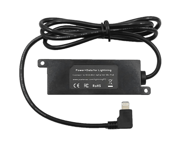
Welcome to the PoE Texas Manual for the GAF-Lightning-PD that gives you wired Power and Data!
The purpose of the manual is to help you quickly and effectively navigate the installation and functions of your new Power Over Ethernet Splitter.
Our goal is to make our products as intuitive and simple to use as possible, so we value your feedback and questions directly to us at service@poetexas.com.  Phone +1-512-479-0317.
Or you’re always welcome to leave questions or comments on our product page: GAF-Lightning-PD.

What’s Inside

PARTS LIST: GAF-LIGHTNING-PD-V3

  • 1 X POE Splitter (Power + Data in 1 cable)


PARTS LIST: GAF-LIGHTNING-PD-V4

  • 1 X POE Converter (Power + Data in 1 cable) USB-C to Lightning Cable


GENERAL INSTALLATION


Your new PoE splitter is designed to be simple to install and set up.  It is small and light enough to leave “inline” with your network cable.  


You may also choose to use the two M3 sized mounting brackets to secure the device to a wall or surface.


Once it is in place, simply follow these steps in order:

1 – Plug the RJ-45 end into an IEEE 802.3af PoE or 48-56 volt passive Power Sourcing Equipment (PSE) with a data source

2 – Ensure the iPad is on and log in

3 – Plug the lightning connector into the iPad

The device will automatically set up the network connection with an iPad and begin charging.  To confirm that, go to the General settings tab and look for the <…> symbol next to Ethernet.


In case you iPad loses its connection due to a reboot or an update follow these steps:

RECONNECTING DATA TO YOUR IPAD.

Take Care Handling the Lightning Connector

To allow our product to be installed in enclosures and tight spaces, we have designed the lightning head at a right angle.  However, that tight design does make the head easier to break if twisted in or out of the iPad. 


To insert the connector into the iPad:

  • Grasp the top an bottom between your pointer finger and thumb
  • Push straight in and pull straight out

Damaging the Lightning Connector

Twisting or jerking the lightning connector out to the side will damage the lighting connector.  At best, it will become intermittent.

At worst, the lightning connector will come out completely.


  • Do not remove by pulling on the cord
  • Do not lever side to side


Thank you for your care with this product!

Getting the Unlock iPad to Use Accessories warning?  

We’ll fix that in the configuration below.

CONFIGURATION

Configuring Your iPad for Wired Data

There are a couple easy steps for configuring your iPad to get the best results when working with wired data.

First, we’re going to enable USB devices to allow charging even when the iPad is “off” or the screen is locked.  

If you you don’t have the most up to date iOS software, take this time to update to iOS 12.2 or later.  Otherwise, it will prevent any connected device from charging or communicating with it after the screen has been locked for an hour.  Here’s how to fix that:


  • Navigate to the Settings tab
  • Select Face ID & Passcode
  • Ensure the USB Accessories button is toggled to “On” meaning you see the green

You can still set up your iPad to not automatically lock on a timer.  When the screen locks if you would like the screen always on. 

  • Go to the Settings icon on your iPad
  • Select Display & Brightness
  • Select Auto Lock
  • Set the limit to Never

Best Practices for iOS Updates

Despite Apple’s excellent reputation for ensuring backward compatibility with their iPads and iPhones, practical experience with a recent iOS update has revealed that even they can miss things which can temporarily lead to disruption of service for your device.   If your device must be reliable 24/7, we recommend these following best practices:

  • Go to Settings -> General -> Software Updates -> Automatic Updates
  • Deselect “Install iPadOS Updates”
  • Before choosing to install the next update, please check into our iOS Compatibility Table to check whether we have finished testing the performance of an new iPadOS version

iOS Compatibility Table

  • Finally, to get emailed live updates on iOS compatibility, subscribe to our mailing list for iOS compatibility

In case of a reboot or shut down of the iPad, some iPad models will not reconnect the data connection of the GAF-Lightning-PD to the iPad.

  • Simply log into the iPad,
  • Disconnect the lightning connector to the iPad
  • Cycle on the PoE port either by disconnecting the network cable or cycling power through the PoE management.
  • Once you reconnect, your iPad will re-establish communications.

If you have remote control of your PoE ports, have someone log into the iPad, then reboot the PoE port.  It may require 2 reboots to reestablish connection.

The splitter will auto-configure the IP settings to default as soon as you connect it up including Dynamic IP addressing.


You can now update these settings with these steps:

Technical Specifications

Product Specifications

Cable connector length 3 Feet
Cable connectors Lightning Male
Data + PoE Ports 1 (Input)
Data Rate 10/100
Dimensions 6x1x1.5 in.
Input voltage 44 volts to 57 volts
LEDs Per Port 1 Green (power) / 1 Yellow (Data)
Max Power for Kit 12 Watts
Max Voltage 5 Volts (output)
Mount Type Wall Mount tabs
Operating Humidity 5% to 90%
Operating Temperature Range -10 – 60C
Output Voltage 5 Volts
PoE Standard IEEE 802.3af

If you find this learning center helpful, like and subscribe on your social channels to learn when we post new guides!

POE-PIHAT

POE-PIHAT

POE-PiHat INSTALLATION MANUAL


Welcome to the PoE Texas Manual for the POE-PiHat!


The purpose of the manual is to help you quickly and effectively navigate the installation and functions of your new Power Over Ethernet Adapter. 

Our goal is to make our products as intuitive and simple to use as possible, so we value your feedback and questions directly to us at service@poetexas.com.  Phone +1-512-479-0317.

Or you’re always welcome to leave questions or comments on our product pages: POE-PiHat.

What’s Inside

PARTS LIST: POE-PiHat

  • 1 X POE ADAPTER


No, unfortunately, this doesn’t come with a case, however it fits most new cases including the official one.

    General Installation

    Your new PoE hat is designed to be simple to install and set up.  Simply orient the correct pins on the Pi, then press it down fully.

    And that’s it.  Once it is in place, simply plug the RJ-45 end into a 48-56 volt passive Power Sourcing Equipment (PSE) with a data source, and the Pi will start to power up automatically.

    **Please note that the PiHat is rated for 12.9 watts.  If you plan to load down the process or and plug devices into all the USB ports, you might find you draw closer to 15 watts.  For that, we recommend our GAT-5v20w with a microUSB connector.

    CONFIGURATION

    There is no configuration necessary with this device.  Simply plug it in and follow the installation instructions.

    Technical Specifications

    Product Specifications

    Certifications CE, FCC
    Connector Types Two 4 pin x 1 mm
    Data Rate 10/100/1000
    Dimensions 2 5/8″ x 1 1/2″ x 3/4″
    Efficiency 90%
    Max Current 270 mA
    Mount Type Board Mounted
    Operating Temperature Range 10-90% non condensing
    OperatingTemperature Range 0 – 40C
    Output Voltage 5 volt
    PoE Mode/Pinout Mode A
    PoE Standard IEEE 802.3af
    Weight 1 oz

    If you find this learning center helpful, like and subscribe on your social channels to learn when we post new guides!

    GAF-PIHAT, GAT-PIHAT

    GAF-PIHAT, GAT-PIHAT

    GAF-PiHat INSTALLATION MANUAL


    Welcome to the PoE Texas Manual for the GAF-PiHat!


    The purpose of the manual is to help you quickly and effectively navigate the installation and functions of your new Power Over Ethernet Adapter. 

    Our goal is to make our products as intuitive and simple to use as possible, so we value your feedback and questions directly to us at service@poetexas.com.  Phone +1-512-479-0317.

    Or you’re always welcome to leave questions or comments on our product pages: GAF-PiHat.

    What’s Inside

    PARTS LIST: GAF-PiHat

    • 1 X PoE Adapter for Raspberry Pi 3B+ and 4
    • 1x Heat guard


    No, unfortunately, this doesn’t come with a case, however it fits most new cases including the official one.

      PARTS LIST: GAT-PiHat

      • 1 X PoE Adapter for Raspberry Pi 4
      • 1x Cooling Fan


      No, unfortunately, this doesn’t come with a case, however it fits most new cases including the official one.

        General Installation

        Your new PoE hat is designed to be simple to install and set up.  Simply orient the correct pins on the Pi, then press it down fully. 

        And that’s it.  Once it is in place, simply plug the RJ-45 end into an IEEE 802.3af PoE or 48-56 volt passive Power Sourcing Equipment (PSE) with a data source, and the Pi will start to power up automatically. For the GAT-PiHat use an IEEE 802.3at PoE switch or an 48v injector.

        Please note that the PiHat is rated for 12.9 watts.  If you plan to load down the process or and plug devices into all the USB ports, you might find you draw closer to 15 watts.  For that, we recommend our GAT-5v20w with a microUSB connector.

        CONFIGURATION

        There is no configuration necessary with this device.  Simply plug it in and follow the installation instructions.

        Technical Specifications

        Product Specifications

        Product Specifications

        Certifications CE, FCC, RoHS
        Connector Types Two 4 pin x 1 mm
        Data Rate 10/100/1000
        Dimensions 2 5/8″ x 1 1/2″ x 7/10″
        Efficiency 90%
        Max Current 2500 mA
        Mount Type Board Mounted
        Operating Humidity 10-90% non condensing
        Operating Temperature Range 0 – 40C
        Output Voltage 5 volt
        PoE Mode/Pinout Mode A/Mode B
        PoE Standard IEEE 802.3af (Passive 48 VDC)
        Weight 1 oz

        If you find this learning center helpful, like and subscribe on your social channels to learn when we post new guides!

        GPOE-Extender

        GPOE-Extender

        GPOE-EXTENDER INSTALLATION MANUAL

        Welcome to the PoE Texas Manual for the Extender Line of Products!

        The purpose of the manual is to help you quickly and effectively navigate the installation and functions of your new Power Over Ethernet Extender.

        Our goal is to make our products as intuitive and simple to use as possible, so we value your feedback and questions directly to us at service@poetexas.com.  Phone +1-512-479-0317.

        Or you’re always welcome to leave questions or comments on our product page: GPOE-Extender


        If you’d like to learn more about our Extender Line of Switches that allow you to extend to multiple devices on one network cable, check out these products: GBT-4-IW and GPOES-EX2005-IP67

        What’s Inside

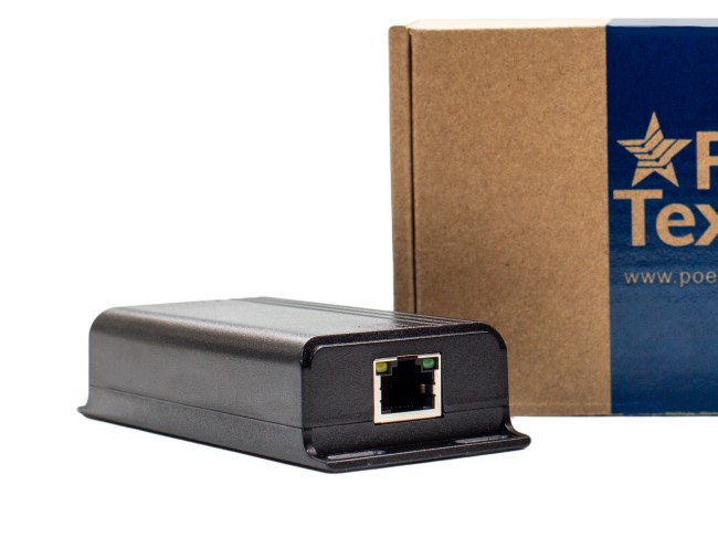
        PARTS LIST: GPOE-Extender

        • 1 X Extender
        • 2 X IP67 glands [required use for proper install]

        Key Features:

        • IEEE 802.3bt Dual Signature, IEEE 802.3at and af compliant
        • 10/100/1000 Mbps Data Rate
        • IP67 rated for outdoor use; water resitant- DO NOT submerge in water [not water proof]

        General Installation

        Your new GPOE-Extender is designed to be simple to install and set up. This unit is designed for indoor and outdoor use. If using outdoors, the unit is water resitant but not water proof, meaning the unit can withstand rain and snow but do NOT submerge the GPOE-Extender in water or other liquids. 


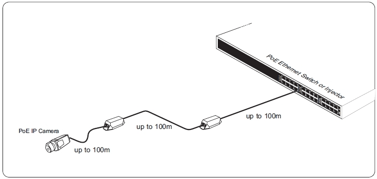
        To install your GPOE-Extender, place the extender inline after your PoE switch or injector (PSE) within a 100m (300 ft) distance from the PSE.  Using a second category cable to run to a second GPOE-Extender or to your powered device within 100m. Please see the diagram below for distance placement. 


        To properly install the GPOE-EXTENDER the IP67 Glands MUST be used on the input and output side of the extender. Use sissors to cut through the gland and wrap the gland around the base of the category cable. Insert the gland into the GPOE-Extender and cover with the metal protector by screwing on. This will assure your extender stays water resistant. For more detail on the install, please watch our youtube video below. Failure to properly install the glands with outdoor usage will lead to water leaks, voiding the warranty on the unit.

        CONFIGURATION

        There is no configuration necessary with this device.  Simply plug it in and follow the installation instructions.

        OR Call a PoE Shifu for assistance +1(512)479-0317

        Technical Specifications

        Product Specifications

        Certifications IEEE 802.3af (PoE), IEEE 802.3at (PoE+), IEEE 802.3bt (PoE++) RoHS Compliant
        Data + PoE Ports 2
        Data Rate 10/100/1000
        Dimensions 209 mm x 53 mm x 37.5 mm
        IP Rating IP67
        Load Regulation 6KV
        Max Power for Kit 60 Watts
        Max. Amps Per Port 1.1Amp
        Mount Type Wall
        Operating Humidity 20%-80% Non-Condensing
        Operating Temperature Range -40 to 65 C
        Output Voltage 55v (Typical)
        PoE Mode/Pinout Mode A
        PoE Standard IEEE 802.3bt
        PoE Standards Supported IEEE 802.3af/at/bt
        Power Input 44 – 57 volts POE
        Storage Temperature -40 to 85 C
        Weight 13.9 oz

        If you find this learning center helpful, like and subscribe on your social channels to learn when we post new guides!

        GBT-4-IW

        GBT-4-IW

        Welcome to the PoE Texas Manual for the GBT-4-IW!

        The purpose of the manual is to help you quickly and effectively navigate the installation and functions of your new PoE Inwall Switch. 

        Our goal is to make our products as intuitive and simple to use as possible, so we value your feedback and questions directly to us at service@poetexas.com.  Phone +1-512-479-0317.

        Or you’re always welcome to leave questions or comments on our product pages: GBT-4-IW.

        What’s Inside

        PARTS LIST: GBT-4-IW

        • 1 X Inwall Switch
        • 2 X Screws for mounting into gang box
        • 1 X front cover plate

        **It does not include a gang box.

        General Installation

        Put it together:

        You can connect any non-PoE, PoE (12 watt), or PoE+ (25 watt) device up to the power budgets listed above based on your PoE switch.

        CONFIGURATION

        There’s nothing to configure.  The GBT-4-IW will automatically network with your infrastructure to receive IP addresses and network protocols.

        Technical Specifications

        Product Specifications

        Certifications CE, FCC, RoHS
        Data + PoE Ports 4
        Data Ports 1
        Data Rate Gigabit
        Dimensions Single Gang US Box
        Display Type Blue LED Status Indicator
        Input Voltage Range 44-56 volts through Uplink Port
        Max Power for Kit 60 watts total
        Mount Type In-wall
        Operating Humidity 5% to 90%
        Operating Temperature Range -10 – 45C
        PoE Method IEEE 802.3bt/4PPoE (Uplink) / IEEE 802.3af LAN
        PoE Mode/Pinout Mode A (-1,2 +3,6)/Mode B (+4,5 -7,8)
        PoE Standard Injector: Passive 4 Pair PoE / Switch IEEE 802.3bt and IEEE 802.3af
        PoE Standards Supported Single Signature IEEE 802.3bt Type 4

        If you find this learning center helpful, like and subscribe on your social channels to learn when we post new guides!

        GAT-USBC-PD

        GAT-USBC-PD

        GAT-USBC-PD-REV2, GAT-USBC-PD-R2V2, & GAT-USBC-PD-R2V3

        (PoE Splitter for USBC Devices)

        Welcome to the PoE Texas Manual for the patent pending GAT-USBC-PD-REV2 (designed for Microsoft Surface and Samsung), GAT-USBC-PD-R2V2, and GAT-USBC-PD-R2V3 (designed for Apple Ipad Pro) that gives you wired Power and Data for your USB Type C devices!

        The purpose of the manual is to help you quickly and effectively navigate the installation and functions of your new Power Over Ethernet Converter.

        Our goal is to make our products as intuitive and simple to use as possible, so we value your feedback and questions directly to us at service@poetexas.com.  Phone +1-512-479-0317.

        Or you’re always welcome to leave questions or comments on our product page: GAT-USBC-PD-R2V3-USBC.

        What’s Inside

        PARTS LIST:

        • 1 X POE+ Converter
        • 1 X USB-C to USB-C (right angle)

        Do you have an iPad with a lightning connector?  No problem.  Our USB-C to Lightning connector allows you to charge and send data to an iPad from our GAT-USBC-PD.

        GENERAL INSTALLATION


        Your new PoE converter is designed to be simple to install and set up.  It is small and light enough to leave “inline” with your network cable.  

        You may also choose to use the four M3 sized mounting brackets to secure the device to a wall or surface.


        Once it is in place, simply follow these steps in order:

        1 – Plug the RJ-45 end into an IEEE 802.3at PoE (POE+) or 48-56 volt passive Power Sourcing Equipment (PSE) with a data source

        2 – Ensure the device you’re connecting to is on and logged in

        3 – Plug the USB-C connector into the device

        The converter will automatically set up the network connection with your device and begin charging.  To confirm that, go to the General settings tab or look for the <…> symbol next to Ethernet.

        CONFIGURATION

        Configuring Your Cisco Enterprise POE Switch for 2 Event PoE Classification

        Yeah, I know that’s a mouthful.  Here’s the simple translation.  Cisco enterprise switches including the 9400 and 9300 models, which is a lot of them, come with a default setting that makes them less compatible PoE+ devices like the GAT-USBC-PD.   You’ll know the setting isn’t right because our device won’t power on correctly, and your device won’t charge.  How frustrating!

        It’s a simple enough fix.  You simply need to configure the ports that will power the GAT-USBC-PD to have 2 event classification.  You can find the Cisco documentation on how to do that here: CONFIGURE MY SWITCH

        Or here are the steps you take after you’ve logged into the terminal. 

        Switch> enable
        Switch# configure terminal
        Switch(config)# interface gigabitethernet2/0/1

        Switch(config-if)# power inline port 2-event
        Switch(config-if)# end

        You can still set up your iPad to not automatically lock on a timer.  When the screen locks if you would like the screen always on.

        • Go to the Settings icon on your iPad
        • Select Display & Brightness
        • Select Auto Lock
        • Set the limit to Never


        The splitter will auto-configure the IP settings to default as soon as you connect it up including Dynamic IP addressing.

        1. Navigate to General Settings, then you’ll see a symbol for the LAN <…>
        2. Select this and you’ll see the option for PoE Texas LAN, select it

        You’ll see your IPV4 IP address information.  If it shows “Automatic”, that means your getting a dynamically assigned IP address.

        If you’d like to reconfigure the IP address, DNS, and HTTP Proxy settings, you can do that by selecting these options.  

        The most used option will be fixing your IP address by selecting the “Automatic” button.

        For the other networks settings, we’d recommend talking to a service provider or give us a call: 512-479-0317 or service@poetexas.com.

        Technical Specifications

        Product Specifications

        Connector Types USB Type C
        Data Rate 10/100/1000
        Dimensions 4.5 x 2 x 1 in
        Efficiency 90%
        Input Voltage Range 44-56 volts (IEEE 802.3at compliant)
        LEDs Per Port Green (POE) / Yellow (USB-C)
        Max Power for Kit 25 watts
        Mount Type Wall or DIN rail clips
        Operating Humidity 5% to 90%
        Operating Temperature Range -10 – 60C
        Output Voltage 5V,2.6A; 9V,1.78A; 12V,1.34A; 15V,1.37A; 20V,1.15A
        PoE Method IEEE 802.3at / PoE+ / Passive 30 watt
        PoE Mode/Pinout Mode A/B
        PoE Standard IEEE 802.3at
        Power Input 25.5 watts
        Weight 3 oz


        If you find this learning center helpful, like and subscribe on your social channels to learn when we post new guides!

        GPOE-4A

        GPOE-4A

        GPOE-4A INSTALLATION MANUAL

        Welcome to the PoE Texas Manual for the GPOE-4A that cost effectively upgrades any non-PoE switch or PoE switch to 30 watt passive PoE!

        The purpose of the manual is to help you quickly and effectively navigate the installation and functions of your new Power Over Ethernet Midspan.

        Our goal is to make our products as intuitive and simple to use as possible, so we value your feedback and questions directly to us at service@poetexas.com.  Phone +1-512-479-0317.

        Or you’re always welcome to leave questions or comments on our product pages: GPOE-4A or GPOE-4A-48v48w.

        Do you have an 8 port model?  Check out our 8 port manual as well.

        What’s Inside

        PARTS LIST: GPOE-4A (No Power Supply)

        • 1 X GPOE-4A

        We do offer this injector by itself without a power supply so you can select a power supply to fit your application needs.

        Or you can select a pre-kitted option below.

        Additional items you’ll need not included:

        1 – Screws for mounting

        2 – Power supply

        3 – Patch cables to the switch and home run cables to the device

        NEED HELP PICKING A POWER SUPPLY?  USE OUR POE CALCULATOR TO CREATE A POWER BUDGET.

        PARTS LIST: GPOE-4A-48v48w

        • 1 X GPOE-4A Midspan Injector
        • 1 X PS-48v48w 48 volt 48 watt DC power supply

        We do offer this injector by itself without a power supply so you can select a power supply to fit your application needs. 

        Additional items you’ll need not included:

        1 – Screws for mounting

        2 – Power supply

        3 – Patch cables to the switch and home run cables to the device

        General Installation

        A midspan like the GPOE-4A is a simple device to add into any network, and the purpose is to add or increase the PoE of your network without having to upgrade or pick a less optimal switch.


        With this wall mounted device, simply mount it near the networking switch you’d like to pair it with.  Then, using a short Ethernet patch cable from the switch’s data port to the LAN port on the PoE midspan.   Then the POE port adjacent to the LAN port will now have that 30 watt potential power budget.

        NOTE: a midspan adds PoE to one data port at a time.  So if you connect LAN 1 to a data port on your switch you’ll have Mode A POE on port 1 of the midspan [wait . . . what’s Mode A mean?].  To get POE on port 2, you need to add a patch cable on LAN 2 back to the switch,  And so on.

        Then connect the POE port to your PoE enabled device.

        WARNING: this is a passive PoE midspan, meaning it does not negotiate the IEEE 802.3af standard before delivering power.  What does that mean for you?  You should only connect the POE ports to a PoE enabled device.  Connecting it to a laptop or other non-PoE device will damage the network card on your device.

        So why even use a passive PoE midspan?  Besides being very cost effective, they’re simple, robust devices that work well even when you forget about them.  So as long as the connected device is PoE and no one can unplug it – say a security camera or wifi access point – it makes sense.

        CONFIGURATION

        There is no configuration necessary with this device.  Simply plug it in.

        The green LED indicates power on.   If the green light begins to blink at any time, it is an indication that one of the POE ports has shorted out or overloaded.

        STEPS:

        1 – Unplug the POE ports one at a time to determine which port is having the issue

        2 – Troubleshoot the port to determine whether the cable or the device is grounded

        Technical Specifications

        Product Specifications

        Data + PoE Ports 4
        Data Ports 4
        Data Rate Gigabit
        Dimensions 4x3x1 in.
        Max. Amps Per Port 1.25
        Mount Type wall
        Operating Humidity 5% to 90%
        Operating Temperature Range -10 – 60C
        PoE Method Passive
        PoE Mode/Pinout Mode A (1,2- 3,6+)
        Power Input 2.1mm DC

        If you find this learning center helpful, like and subscribe on your social channels to learn when we post new guides!

        GAF-5v10w; GAF-12v12w; Cable Accessories

        GAF-5v10w; GAF-12v12w; Cable Accessories

        5 Volt and 12 Volt IEEE 802.3af PoE Splitters

        What’s Inside

        PARTS LIST: GAF-5V10W

        • 1 X POE SPLITTER

        The GAF-5V10W comes with a male 1.35mm x 3.5mm DC barrel connector.

        PARTS LIST: GAF-USB

        • 1 X POE SPLITTER
        • 1 X MICRO USB ADAPTER STRAIGHT (ANDROID FAST CHARGE)
        • 1 X FEMALE USB (APPLE FAST CHARGE)

        The GAF-USB comes with the adapters you need for fast charging an Android or Apple tablet.  The female USB adapter will charge any 5 watt USB enabled device, but it will only fast charge (12 watts) an Apple device.

        PARTS LIST: GAF-Lightning

        • 1 X  1.35mm DC to Lightning Adapter

        The GAF-Lightning comes with the adapters you need for fast charging an Apple tablet or phone.  

        PARTS LIST: GAF-12v12w

        • 1 X POE SPLITTER FOR 12 VOLT 1AMP (12 WATT) DC POWERED DEVICES [DC BARREL SIZE 2.1mm X 5.5mm]

        PARTS LIST: GAF-PTZOptics

        • 1 X POE SPLITTER FOR 12 VOLT 1AMP (12 WATT) DC POWERED DEVICES [DC BARREL SIZE 2.1mm X 5.5mm]
        • 1 X 2.1mm X 5.5mm to EIAJ-04 Connector Adapter

        General Installation

        Your new PoE splitter is designed to be simple to install and set up.  It is small and light enough to leave “inline” with your network cable.

        A adhesive or screw backed cable anchor is sufficient to hang the adapter on a wall or enclosure.

        Once it is in place, simply plug the end of your category cable into an IEEE 802.3af PoE or 48-56 volt passive Power Sourcing Equipment (PSE) with a data source (optional), and the other end into your device such as a camera, Raspberry Pi, Ipad, Android tablet, or any compatible device.

        Please note that the female USB adapter is configured to fast charge Apple devices only.  It will still charge Android or other USB enabled devices up to 5 watts.  However, it won’t provide the 10-12 watts of fast charge.

        I Want Power and Data to My iPad!

        Visit Our GAF-Lightning-PD Page

        The GAF-Lightning-PD combines the power and data from Power Over Ethernet onto a lightning connector specially designed to fit into tight enclosures to charge the iPad Air and iPad Mini.

        I Want Power and Data to My Android/Windows Device

        Check out our GAT-USBC-PD Page on PoE to USB Type C devices that transmits both power and data!

        CONFIGURATION

        There is no configuration necessary with this device.  Simply plug it in.


        The yellow LED indicates power on the primary side (your PoE side).  The green indicates power on the secondary (5 volt side).

        Technical Specifications

        Product Specifications

        Cable connector length 8.5 inches
        Cable connectors RJ45 Male, 1.35mm Male DC
        Data + PoE Ports 1 (input)
        Data Ports 1
        Data Rate Gigabit
        DC connector 1.35mm male (power out)
        Dimensions 6x1x1.5 in.
        Input voltage 44 volts to 57 volts
        Max. Amps Per Port 2
        Operating Humidity 5% to 90%
        Operating Temperature Range -10 to 60°C
        Output Voltage 5 or 12 volts
        PoE Method Active
        PoE Mode/Pinout Mode A (-1,2 +3,6)/Mode B (+4,5 -7,8)
        Power Input Female RJ45
        Weight 1 oz

        If you find this learning center helpful, like and subscribe on your social channels to learn when we post new guides!

        GPOE-1B

        GPOE-1B

        GPOE-1B

        (PoE Gigabit Injector)

        Welcome to the PoE Texas Manual for the GPOE-1B that cost effectively upgrades any non-PoE switch or PoE switch to 30 watt passive PoE!

        The purpose of the manual is to help you quickly and effectively navigate the installation and functions of your new Power Over Ethernet Midspan.

        Our goal is to make our products as intuitive and simple to use as possible, so we value your feedback and questions directly to us at service@poetexas.com.  Phone +1-512-479-0317.

        Or you’re always welcome to leave questions or comments on our product pages: GPOE-1B or GPOE-1B-48V15W or GPOE-1B-48V30W or GPOE-1B-24V30W

        What’s Inside

        GPOE-1B

        PARTS LIST:

        • 1 X GPOE-1B

        This Injector is sold without a power supply. We do offer pre-kitted options, see below.


        Additional items you’ll need not included:

        1 – Screws for mounting

        2 – Power supply

        3 – Patch cables to the switch and home run cables to the device


        NEED HELP PICKING A POWER SUPPLY?  USE OUR POE CALCULATOR TO CREATE A POWER BUDGET.

        GPOE-1B-48V15W


        PARTS LIST:

        1 X GPOE-1B Midspan Injector

        1 X PS-48v15w 48 volt 15 watt DC power supply


        We do offer this injector by itself without a power supply so you can select a power supply to fit your application needs. 


        Additional items you’ll need not included:

        1 – Screws for mounting

        2 – Power supply

        3 – Patch cables to the switch and home run cables to the device

        GPOE-1B-48V30W


        PARTS LIST:

        • 1 X GPOE-1B Midspan Injector
        • 1 X PS-48v30w 48 volt 30 watt DC power supply 


        Additional items you’ll need not included:

        1 – Screws for mounting

        2 – Power supply

        3 – Patch cables to the switch and home run cables to the device

        GPOE-1B-24V30W

        PARTS LIST:

        • 1 X GPOE-1B Midspan Injector
        • 1 X PS-24v30w 24 volt 30 watt DC power supply

        We do offer this injector by itself without a power supply so you can select a power supply to fit your application needs. 


        Additional items you’ll need not included:

        1 – Screws for mounting

        2 – Power supply

        3 – Patch cables to the switch and home run cables to the device

        General Installation

        CONFIGURATION

        There is no configuration necessary with this device.  Simply plug it in.

        The green LED indicates power on.   If the green light begins to blink at any time, it is an indication that one of the POE ports has shorted out or overloaded.

        STEPS:

        1 – Unplug the POE ports one at a time to determine which port is having the issue

        2 – Troubleshoot the port to determine whether the cable or the device is grounded

        Technical Specifications

        Product Specifications

        Data + PoE Ports 1
        Data Ports 1
        Data Rate Gigabit
        Dimensions 1x1x2 in.
        Max. Amps Per Port 650 mA
        Mount Type wall
        Operating Humidity 5% to 90%
        PoE Method Passive
        PoE Mode/Pinout Mode B (+4,5 -7,8)
        PoE Standard N/A
        Power Input 2.1mm DC

        If you find this learning center helpful, like and subscribe on your social channels to learn when we post new guides!

        GPOE-1AB-Y

        GPOE-1AB-Y

        GPOE-1AB-Y; GPOE-6AB

        (PoE 2.5 Gigabit Injector)

        Welcome to the PoE Texas Manual for the GPOE-1AB and GPOE-6AB that cost effectively upgrades any non-PoE switch or PoE switch to 60 watt passive PoE!

        The purpose of the manual is to help you quickly and effectively navigate the installation and functions of your new Power Over Ethernet Midspan.

        Our goal is to make our products as intuitive and simple to use as possible, so we value your feedback and questions directly to us at service@poetexas.com.  Phone +1-512-479-0317.

        Or you’re always welcome to leave questions or comments on our product pages: GPOE-6AB GPOE-1AB-Y  

        What’s Inside

        PARTS LIST:

        • 1X GPOE-1AB
        • 1X 2.1-2.1-Y CABLE

        We do offer power supplies so you can select a power supply to fit your application needs or call us for a recommendation +1-512-479-0317.

        Additional items you’ll need not included:

        1 – Screws for mounting

        2 – Power supply

        3 – Patch cables to the switch and home run cables to the device

        NEED HELP PICKING A POWER SUPPLY?  USE OUR POE CALCULATOR TO CREATE A POWER BUDGET.

        GPOE-6AB

        We do offer this injector with a variety of power supplies so you can select a power supply to fit your application needs.

        AVAILABLE POWER SUPPLY OPTIONS:

        • GPOE-6AB-Y
        • GPOE-6AB-48V60W [Includes 48 volt 6o watt Power Supply]
        • GPOE-6AB-24v120w [Includes 24 volt 120 watt Power Supply]
        • GPOE-6AB-48v120w [Includes 120 watt Power Supply]
        • GPOE-6AB-56V120W [Includes 56 volt 120 watt Power Supply]
        • GPOE-6AB-48V30W [Includes 48 volt 30 watt Power supply]

        Additional items you’ll need not included:

        1 – Screws for mounting on a wall (optional)

        2 – Power supply [see available options above]

        3 – Patch cables to the switch and home run cables to the device

        NEED HELP PICKING A POWER SUPPLY?  USE OUR POE CALCULATOR TO CREATE A POWER BUDGET OR CONTACT A POE-Shifu 512-479-0317.

        PARTS LIST:

        • 1X GPOE-6AB
        • 1X 2.1-2.1-Y CABLE
        PARTS LIST:

        • 1X GPOE-6AB
        • 1X 24 volt Power Supply
        PARTS LIST:

        • 1X GPOE-6AB
        • 1X 48 volt Power Supply

        General Installation

        CONFIGURATION

        There is no configuration necessary with this device.  Simply plug it in.

        The green LED indicates power on.   If the green light begins to blink at any time, it is an indication that one of the POE ports has shorted out or overloaded.

        STEPS:

        1 – Unplug the POE ports one at a time to determine which port is having the issue

        2 – Troubleshoot the port to determine whether the cable or the device is grounded

        Technical Specifications

        GPOE-1AB-REV2-Y

        Product Specifications

        Adapters included 2.1mm x 5.5mm Y-Cable
        Data + PoE Ports 1
        Data Ports 1
        Data Rate 2.5 Gigabit
        DC connector 2.1mm x 5.5mm DC Standard
        Dimensions 1x1x4 in.
        LEDs Per Port 1
        Management Port None
        Max. Amps Per Port 0.9A / 1.8A (With Y-Cable)
        Mount Type Wall Mount
        Operating Humidity 5% to 90%
        Operating Temperature Range -10 – 60C
        PoE Configurable Per Port No
        PoE Method Passive
        PoE Mode/Pinout Mode A (-1,2 +3,6)/Mode B (+4,5 -7,8)
        PoE Standard 802.3af
        Weight 10oz

        GPOE-6AB-Y

        Product Specifications

        Adapters included 2.1 x 5.5mm Y-Cable
        Data + PoE Ports 6
        Data Ports 6
        Data Rate 2.5 Gigabit
        Dimensions 6 x 3 x 1 in.
        Input Voltage Range 12 – 56 Volts DC
        Max. Amps Per Port 650 mA / 1.25 (With Y-Cable)
        Mount Type Wall
        Operating Humidity 5% to 90%
        Operating Temperature Range -10 – 60C
        PoE Method Passive
        PoE Mode/Pinout Mode A (-1,2 +3,6)/Mode B (+4,5 -7,8)
        Power Input 2.1 x 5.5 mm DC x2

        GPOE-6AB-48V60W

        Product Specifications

        Certifications UL/CE/FCC
        Data + PoE Ports 6
        Data Ports 6
        Data Rate 2.5 Gigabit
        Dimensions 6 x 3 x 1 in.
        Input voltage 48 Volts
        LEDs Per Port 1
        Max Amps Per Kit 1.25 Amps
        Max Power for Kit 60 Watts
        Max. Amps Per Port 650 mA / 1.25 (With Y-Cable)
        Mount Type Wall
        Operating Humidity 5% to 90%
        Operating Temperature Range -10 – 60C
        Output Voltage 48 volts
        PoE Method Passive
        PoE Mode/Pinout Mode A (-1,2 +3,6)/Mode B (+4,5 -7,8)
        PoE Standard 802.3af
        Power Input 2.1 x 5.5 mm DC
        Power Supplies PS-48v60w
        Weight 21oz

        GPOE-6AB-48v120w

        Product Specifications

        Certifications UL/CE/FCC
        Data + PoE Ports 6
        Data Ports 6
        Data Rate 2.5 Gigabit
        Dimensions 3x4x6 in.
        LEDs Per Port 1
        Max Amps Per Kit 2.5 Amps
        Max Power for Kit 120 Watts
        Max. Amps Per Port 650 mA
        Mount Type wall
        Operating Humidity 5% to 90%
        Operating Temperature Range -10 – 60C
        Output Voltage 48 volts
        PoE Method Passive
        PoE Mode/Pinout Mode A (-1,2 +3,6)/Mode B (+4,5 -7,8)
        PoE Standard 802.3af
        Power Input 2.1mm DC
        Power Supplies WS-PS-48v120w
        Weight 26 oz

        GPOE-6AB-56V120W

        Product Specifications

        Certifications UL/CE/FCC
        Data + PoE Ports 6
        Data Ports 6
        Data Rate 2.5 Gigabit
        Dimensions 6 x 3 x 1 in.
        Input voltage 56 Volts
        Max Amps Per Kit 5 Amps
        Max Power for Kit 120 Watts
        Max. Amps Per Port 650 mA / 1.25 Amp (With Y-Cable)
        Mount Type Wall
        Operating Humidity 5% to 90%
        Operating Temperature Range -10 – 60C
        Output Voltage 56 Volts
        PoE Method Passive
        PoE Mode/Pinout Mode A (-1,2 +3,6) / Mode B (+4,5 -7,8)
        Power Input 2.1 x 5.5 mm DC
        Power Supplies PS-56v120w

        GPOE-6AB-48V30W

        Product Specifications

        Certifications UL/CE/FCC
        Data + PoE Ports 6
        Data Ports 6
        Data Rate 2.5 Gigabit
        Dimensions 6 x 3 x 1 in.
        Input voltage 24 Volts
        Max Amps Per Kit 2.5 Amps
        Max Power for Kit 60 Watts
        Max. Amps Per Port 650 mA / 1.25 (With Y-cable)
        Mount Type Wall
        Operating Humidity 5% to 90%
        Operating Temperature Range -10 – 60C
        Output Voltage 24 volts
        PoE Method Passive
        PoE Mode/Pinout Mode A (-1,2 +3,6)/Mode B (+4,5 -7,8)
        Power Input 2.1 x 5.5 mm DC
        Power Supplies PS-24v60w

        GPOE-6AB-24v120w

        Product Specifications

        Certifications UL/CE/FCC
        Data + PoE Ports 6
        Data Ports 6
        Data Rate 2.5 Gigabit
        Dimensions 6 x 3 x 1 in.
        Input voltage 24 Volts
        Max Amps Per Kit 5 Amps
        Max Power for Kit 120 Watts
        Max. Amps Per Port 650 mA / 1.25 Amp (With Y-Cable)
        Mount Type Wall
        Operating Humidity 5% to 90%
        Operating Temperature Range -10 – 60C
        Output Voltage 24 volts
        PoE Method Passive
        PoE Mode/Pinout Mode A (-1,2 +3,6) / Mode B (+4,5 -7,8)
        Power Input 2.1 x 5.5 mm DC
        Power Supplies PS-24v120w

        If you find this learning center helpful, like and subscribe on your social channels to learn when we post new guides!

        AF-Lightning

        AF-Lightning

        AF-LIGHTNING

        (PoE to Lightning Power Only)

        Welcome to the PoE Texas Manual for the AF-Lightning that delivers PoE power to an iPad!

        The purpose of the manual is to help you quickly and effectively navigate the installation and functions of your new Power Over Ethernet Splitter. 

        Our goal is to make our products as intuitive and simple to use as possible, so we value your feedback and questions directly to us at service@poetexas.com.  Phone +1-512-479-0317.

        Or you’re always welcome to leave questions or comments on our product pages: AF-Lightning.

        What’s Inside

        PARTS LIST: AF-Lightning

        • 1 X POE SPLITTER


        That’s all you’ll need.

        General Installation

        Your new PoE switch is designed to be simple to install and set up. You should only need at most a Philips head screw driver. To power it on, plug the power cable in the back.

        Since this is an IEEE 802.3at (PoE+), you can just start plugging devices into it to eight PoE ports on the left hand side marked 1 through 8.

        Ports 9T and 10T are the Gigabit uplink ports where you connect back to your router or main network switch. Ports 9S and 10S are for Small Form-factor Pluggable (SFP) fiber optic ports. If you’re not familiar with fiber optic connections, you can leave the little plastic plugs installed.

        I Want Power and Data to My iPad!

        Visit Our GAF-Lightning-PD Page

        The GAF-Lightning-PD combines the power and data from Power Over Ethernet onto a lightning connector specially designed to fit into tight enclosures to charge the iPad Air and iPad Mini.

        I Want Power and Data to My Android/Windows Device

        Check out our GAT-USBC-PD Page on PoE to USB Type C devices that transmits both power and data!

        CONFIGURATION

        There is no configuration necessary with this device.  Simply plug it in.


        The yellow LED indicates power on the primary side (your PoE side).  The green indicates power on the secondary (5 volt side).

        Technical Specifications

        Product Specifications

        Cable connector length 8.5 inches
        Cable connectors Apple Lightning Male
        Data Rate N/A
        Dimensions 6x1x1.5 in.
        Input voltage 44 volts to 57 volts
        Operating Humidity 5% to 90%
        Operating Temperature Range -10 – 60C

        If you find this learning center helpful, like and subscribe on your social channels to learn when we post new guides!

        Break the Ethernet Barrier

        Break the Ethernet Barrier

        BREAK THE ETHERNET BARRIER WITH PoE

        Go ahead . . . hit the easy button just this once.

        INTRODUCTION

        Have you hit the Ethernet barrier  – 330 ft – and still need more distance?

         If you’re like many people, myself included, a sense of betrayal comes with discovering for the first time that the world spanning internet you see coming into your computer can only travel 100 meters or 330 ft on Ethernet cable.  You ask yourself, “really?  Three hundred or so feet is as far as you can get?”  Now you’re job is just that much harder.

        Fortunately the real answer to that question is “most of the time”. 

         When Power Over Ethernet gets involved, you can stretch your data signal – and even the power – much further . . . up to about a half a kilometer.  We’ll cover in this white paper how to break your Ethernet barrier to send power and data much further than conventional wisdom allows.

        HOW THIS IS ORGANIZED:

        Please, please, don’t read this whole thing straight through because there’s a lot of information in here that you likely don’t need.   We’ve organized this white paper into different sections so you can navigate to just the sections you need and no more.  Pick which sections below you need based on what you already know:

         EXPLORER: If you know nothing about PoE and how to extend your data signal, start with the CONCEPTS to learn how PoE extensions work
        SOPHOMORE: If you have the concepts down but aren’t quite sure how and went to apply them, go to the APPLICATIONS section
        EXPERT: You know the concepts and how you should apply it, but you have questions about the details of how to make this work in your application, see CONFIGURATIONS
        BEFUDDLED: You’ve already tried making your application work, now you need help figuring what went wrong, or you’re trying to avoid some common mistakes, head to TROUBLESHOOTING
        CURIOUS: Regardless of where you’re at, you can always speak to a PoE Shifu (master) by making time for a CONSULTATION

        CONCEPTS

        Why do I have to extend my Ethernet?

        For a full explanation let’s get Physical (#engineerjoke).  First, the Ethernet Physical Layer – in plain English how we actually send signals over copper wires – works by sending really, really fast pulses of + 2.5 and – 2.5 volts of electricity.   When the volts are HIGH (2.5 volts) we call it a 1.  When the volts are LOW (-2.5 volts) we call it a 0.  Thus a bit of binary is born!

        Ah the magic of logic.  And boys and girls, when a 1 and 0 get together and love each other very much, 8 times to be exact, we call it a byte.

        But . . . even the best wires in the world have some resistance.  What starts out in the beginning as 2.5 volts wears away as it trudges down the copper wires of Category cable.  Eventually the electrons have gotten so tired they stop being excited at all.  We can all blame Georg Simon Ohm for this.  He’s the one who made Ohm’s Law.

        To help us deal with our grief our good friends at IEEE (pronounced I – triple – EEE) set a standard that, as long as you’re on CAT 5 or higher cable, your network device has to at least send and receive signals that can travel 100 m (330 ft).  So, that’s what we all do. 

         For my detail oriented friends, yes, of course some brave souls have made their switches or cables to go further than the minimum.  But, like all good standardized testing situations, if you can just do the minimum, why wouldn’t you?

        All very interesting, you say, but what has Power Over Ethernet got to do with how far Ethernet signals can travel?

         I’m so glad you asked.  Remember that measly +2.5 and – 2.5 volt signal?  Well, with Power Over Ethernet the signal gets to ride on a super charged tsunami of power up to 56 volts.  Much like a real tsunami, that wave can travel much, much further.  Yes, the 2.5 volt signal still tuckers out at about 100 meters, but we can use that tsunami of power to create a truck stop where the 2.5 volt signal can get a shot of caffeine, stretch its legs, and head out for another 100 meters.  Then, when it gets tired again, we boost the signal again.  Rinse and repeat until the 56 volts goes too far to keep powering devices.

         How far is that?  

         Depending on what you’re powering at the other end, it’s about a half a kilometer.

        Saving Time and Money

        Here’s where you can save time and money with PoE.  If you need to get your data signal just a little bit further, you could buy a media converter to change your Ethernet signal into a wireless backhaul (think really powerful wifi access points that beam their data along a line of sight) or into fiberoptic cable or into some analog signal on coaxial cable.   But I still haven’t found anyone handing out free media converters (please comment on this blog if you know where they do ’cause I want them).  So, why pay to change your data into a wireless signal or convert to fiber optic when you can just go a little further with PoE?

        In the next section, I’ll discuss the applications where leveraging PoE will save you time and money over other data transmission options.

        APPLICATIONS

        WISP WITHOUT Line of Sight

        You’ve done the hard work to get internet service to literally almost the last mile, but terrain, trees, or a structure block line of sight for your wireless back haul.  What options are you left with?

        • Add another wireless repeater station to jump around or over the obstruction 
        • Find another tower with line of site that has less than optimal conditions or will cost you more
        • Run an extra long PoE run to the signal side of the obstruction

        With the right chain of PoE Extenders, you can literally get around any obstacles in the last 900 ft in your Point to Point or Point to Multi Point network. 

        We’ll cover a variety of configurations including some bonus Cambium alternatives we haven’t found anywhere else.

        A Remote Security Camera

        You’re trying to find the right place to put an exterior mounted security camera on a large property.  For some reason you don’t want all your security cameras to be within 300 ft of the nearest switch.  As long as you’re less than a 990 ft run, you can run the camera power and data to where you want cameras to be.

        The Final Few Meters (or Feet)!

        You’ve done all the calculations on a particular run, and it’s long but doable.  Then you find out some doofus put an elevator shaft in the way.  There’s no way to make the run without getting dangerously close or over the 100 meter (330 ft) barrier.  Do you take the risk on the quality of the switch and cable and just make the run? 

         Do you really want to get pestered for the rest of time by complaints about how this one device is never really reliable?  

        Get yourself a PoE Extender!

        CONFIGURATIONS

        Power Over Ethernet up to 200 Meters (660 ft)
        You’re ready to break the Ethernet Barrier: You only need to take PoE (IEEE 802.3af) or PoE+ (IEEE 802.3at) or even Passive (24 or 48 volt) PoE something over the 100 meter limit.  Let’s make sure we think it through so you don’t have to keep running to your “Home Depot” to get more parts.  By the way, I was told once that they have help groups for people who can’t stop going to Home Depot. 

        Considerations:

        • Where can you locate the PoE Extender?  Will it be inside or outside?
        • Do you need waterproof, or will it be inside a building?
        • How and where will you mount it just in case you ever need to get back to it?
        • What am I powering?  Does it need plane jane PoE or PoE+?
        • Does it need 10/100 data or Gigabit? 

        You use that information to select which extender fits your needs.  You can click the image below to review the options we can offer.

        Rather than tell you all the parts you know you’ll need.  Here’s a parts list you might forget:

        • Depending on how you’re mounting it, you’ll want mounting screws
        • Extra RJ-45 connectors – male and/or female
        • Don’t forget the extra cable!
        • Wall box?  Punch down tools?

        Unless you’re doing doing something crazy like wireless backhaul or some unique PoE standard, it’s as simple as plugging the power and data from your switch or injector into the “In” side and your end device into the “Out” side.  E viola!

        PoE+ Up To 990 Ft (300 meters)
        Rinse and Repeat: The only real difference with going further is how much power you have at the Power Sourcing Equipment (PSE) and how much power you need at the other end.   

        How far can you go?  Our diagram to the left tells you in general terms how far you can go with extenders.  Just keep in mind you will use up power as you add Extenders.   

         If you want to get more precise, you can use our PoE Calculator to determine the loss along the cable.   Rule of thumb: add 3 watts of power to the power consumed by your Powered Device (PD) for every extender you add.  You can see exactly when you cross the 42 volt minimum threshold, and PoE has run its course.

        24 Volt and/or Passive PoE (Ubiquiti or Mikrotik)

        The Wild Child: Frankly, if you don’t immediately recognize 24 volt PoE or Passive PoE, don’t worry about it.  Head back to the previous 2 configurations.  24 volt passive PoE is a misunderstood and often maligned type of PoE that I personally like,  but you don’t just happen to “have it”.  Back haul equipment from a few suppliers like Ubiquiti or Mikrotik use this type of PoE.

         If you do have 24 volt or Passive PoE, then we have the extender for you.  You’ll need a female RJ45 to connect into the device and a male RJ45 on the output.  This extender will pass the same PoE as it receives, less the line losses.  I recommend checking your run on the PoE Calculator, and add 3 watts to the Powered Device (PD) for the extender.  A note on this, though.  24 volt power runs out a lot quicker than 48 or 56 volt power.  It’s unlikely you’ll be able to get more than one extender in the system.

         If you’d like to go further, you can.  Simply use the extender  you prefer with 48 volt or 56 volt power.  Then, at the other end use the GAT-24v25w to convert the power back to 24 volt passive.

        Cambium EPMP 450

         The One, the Only, Cambium: Okay, the fact that you’re here reading this is a testament to how well the EPMP 450 works even if it’s a pain in the #%$ to hook up because it uses a very unique type of PoE.  But even here PoE Texas can help.

         The PoE-Extender will work with an EPMP 29 volt reverse polarity injector if you’re just going 200 m (660 ft).

         However, if you go longer like we mentioned above you can combine a 48  volt Mode B Injector or Switch to extend the power up to 990 ft (300 m), then at the EPMP 450 end you add a 48 volt PoE to 24 volt PoE converter (GAT-24v25w) with a Polarity Reversing Cable (CS-RJ45).  See the schematic to the left.  Boom!  EPMP extended!

        TROUBLESHOOTING

        Need Troubleshooting Tools?

        Check out our line of affordable, easy to use troubleshooting tools.

        Troubleshooting Power (No Lights, nothing): 
        1 – Are you using the right PoE with the right Extender?  See Configuration Sections about the different types of PoE you could encounter.
        2 – Double check your run length to make sure you have exceeded the amount of power you can transmit over the run length.  Start with the PoE Calculator.  Remember to add the extenders into the power load (estimate 3 watts per extender).  Do you drop too low (<42 volts) at the PD end?   You can double check reality with a PoE-Tester.
        3 –  Confirm your switch and extender have the same Mode and Polarity.  What is Mode?   Basically, make sure you’re negotiating on Mode A from your switch/injector if your extender is Mode A.
        4 – Have you done a cable check to make sure you’re terminated properly?  At this point, you can also short cut test with a PoE Tester which will turn on your PoE port.

        Nothing Happens When I Plug It In: 

        In the immortal words of the Hitchhiker’s Guide: DON’T PANIC.  We can get through this.  Grab your towel.

        Check out the troubleshooting tips here.  Then, before you go all Office Space  (Fast Fact: Office Space was based in Austin) on the equipment, you can always call our Austin-based Technical Support team to get some live support: 512-479-0317

        Troubleshooting Data (Lights are on, but no one is home):

        1 – Pull out your cable tester to make sure you have your pins terminated correctly.  Did you intend to do a cross over cable?
        2 – Do a simple “ping” to your end device to see if you have any communication.
        3 – Okay, this may sound silly, but I’ve done this often.  Double check where you’ve plugged into the network.  Is there where it can get the right connectivity?
        4 – Did you do the right set up for your device before you connected it to the network?  Some devices (ahem, Ubiquiti) require you to do a set up directly connected to a computer before you add it to your network.  Double check you device.

        CONSULTATION

        We Can Talk You Through This

        Just Contact Us to Get More Help

        PoE Basics

        PoE Basics

        PoE Fundamentals

        Whether You’re a Pro or New to PoE, Build Your Core Knowledge

        I’ll start by saying that I love Power Over Ethernet (PoE). 

        Yeah, yeah, it’s what I do for a living, but, really, how cool is it that you can take the ethernet cable you have in your wall and get it to power up cameras, iPads, or even TV’s?  I see PoE as Potential (okay, yeah, I couldn’t resist the nerd joke, and be forewarned they keep coming).

        In all seriousness, though, Power Over Ethernet can save you 30% on any given project where you would otherwise have to call a licensed electrician out to pull a permit just to put an outlet somewhere so you can hang a camera.  Even better, because PoE runs  on low voltage power (less than 56 volts) you can safely do the work yourself, or at least get your techie nephew to do it.

        If it’s so cool, why doesn’t everyone do this all the time?  Frankly I’m stumped.  However, I blame it on it sounding too technical because it has to do with computers talking to each other.

        That ends today. I help a lot of people find the right PoE solution, and believe me when I say you can understand PoE. Once you have a few basic terms and principles, you’ll blow minds! To make that magic happen for you I will simplify Power Over Ethernet (PoE) in an easy to understand way even if you’ve never worked on a network before.

        Let’s start off with a pronunciation guide.  This is worth your time.  You drop this on your friends and coworkers, and you become the de facto expert on PoE. 

        • PoE – pronounced PEE – OH – EEE.  Not like Edgar Allan “Poe”.
        • IEEE 802.3af – pronounced EYE TRIPLE EEEE EIGHT OH TWO DOT THREE AYE EF.
        • Okay, so say it with me now . . .  EYE TRIPLE EEEE EIGHT OH TWO DOT THREE AYE EF.

        Great work!!

        So what does that all mean?  Working from the ground up (another engineer joke!), PoE means putting electricity onto an ethernet cable along with a data signal.  You can use that electricity to power all kinds of things: cameras, lights, wifi access points, iPads, phones, TV’s, computers, media players, Raspberry Pi’s.  Warning: once you get into what you can power with PoE, it goes deep, like X-Files deep.
        Oh, about the IEEE thing (yeah, you heard how cool you sound saying it).  Simply put, you have a very smart guy making cameras and you have another smart guy like me – ahem, why thank you – making devices that can power those devices over a network cable.  To make sure we all work together without having to constantly fight over things, we called our friends at the Institute of Electrical and Electronics Engineers (IEEE – “EYE TRIPLE EEE”) and asked them to help us create a standard way of doing things.  They agreed and added us to the 802nd section part three subsection “af” of their standard.
        You don’t need to read it, but if you do – SPOILER ALERT – data and power get together by the end.
        That standard is how engineers agree how the PoE will work, so we both make devices that talk the same PoE.  As time passed we kept coming up with better and better ideas, like MORE POWER!  So now we have a few more standards.  Here’s a table of the PoE standards as they stand today (don’t worry, I will explain it all so just bask in the glory of it):
        PoE Type or Standard Nickname Power Per Port
        (at the device)
        Types of Devices
        IEEE 802.3af PoE 12.9 watts
        IP Cameras
        IP phones
        iPads and Tablets
        (<10″)
        IEEE 802.3at PoE+ 25.5 watts
        Outdoor PTZ Cameras
        Dual Radio Wifi Access Points
        USB Type C phones and tablets
        (>10″)
        IEEE 802.3bt PoE++
        4Pair PoE
        79 watts
        Televisions
        Lights
        Blinds
        Laptops
        *Passive PoE 24 Volt PoE
        Passive
        Up to 55 watts
        Ubiquiti or Mikrotik
        Wireless Internet PtP or PtMP
        (big Wifi Radios)

        *Passive PoE can operate anywhere from 12 volts up to 58 volts. You’ll want to check your specifications carefully to make sure they match your device.

        Have no fear.  You can use a device called a PoE Splitter to change PoE into almost any kind of power you need: USB, 12 volt DC, 19 volt DC, USB Type C.  So find out what kind of power you need, then get a splitter for it.
        The real difference between the types of PoE is how much power your devices need called out in Watts.  What you need to know is that the watts are how much power a device consumes to do its job.  The last column shows you the kind of devices each power level can support.


        And  that, my friends, is all you need to know.  Seriously.  When it’s all said and done, you just need to make sure you pick a Powered Device (PD) like a camera or media controller that matches the standard of the Power Sourcing Equipment (PSE).  You like how I snuck . . . sneeked . . . er . . . snooked some more vocabulary in there?


        “But how do I do that?” you ask.  I’ll break it down bullet point style.  Let’s say you’re looking to add a new camera or any device to your network.
        • First, go find the datasheet.  Don’t Panic.  Every engineer makes a datasheet because its their way of bragging.  It’s like they’re street racers with their tricked-out muscle cars, they want you to know what they’ve got under the hood.  Typically, you can find PoE in the Electrical section.  You’ll find something like “POE” or “IEEE 802.3 af”.  That tells you what kind of PoE your new toy has.
        • Second, select a type of Power Sourcing Equipment (PoE), that’s your PoE switch or midspan (injector).  What’s a switch and what’s a midspan you ask?  They look a lot alike, but don’t be fooled.  They’re different animals with different purposes like a king snake and a coral snake (Krykie, she’s a beauty!  I’m going to pick her up!).

        Why use a Midspan when I can just buy a PoE switch?

        There are two situations where a midspan injector makes more sense:


        1) Let’s say you have your network all set up, and it’s working great.  All the ports are forwarding, Quality of Service (QoS) is great, and everything has been working for a while.  If you’re like me, the guy who set up the network has gone all Jason Bourne on me which means I’ll never find him again.  Then you need to add PoE to it, or you need to add PoE+ to your PoE switch because you just need that little extra power.  Do I really want to try to pull out that switch that I paid a lot of money and headache to get configured to add a few PoE+ devices?  At this point, it’s not about the money, it’s about the headache of nothing working for a month while we get it all sorted out again.  Or do I just add a midspan in a few minutes and forget about it.


        2) You don’t want to have to buy a switch that doesn’t have the features you want just because it can do the PoE you want.  We see this more often than you’d think.  For example, you have an NDI switch that doesn’t have PoE or doesn’t do PoE+.  You need that PoE power for your streaming camera.  Do you buy an NDI switch that may be way more than you need with PoE+ or just use a midspan to add it to the switch you know and love?
        • Finally, once you know your switch or midspan is compatible, then make sure you have enough ports and power budget for all your PoE devices on your PSE.   Most switches and some midspans don’t have enough total power budget to give you full PoE power on all ports at the same time.  Why?!  you may ask.  It comes down to cost and how much you’ll really use each port.  Your Toyota Corolla technically can go to 120 mph, but you really use it to get to work and back.  If you really wanted to go 120 mph, you upgrade a Porsche or Corvette or something truly awesome.   

        There’s a catch . . . this part takes . . . gasp . . . math.  I know you swore you would never touch a calculator again when you got out of school.  Believe me.  It’s not that bad.

        Simple Method:

        Add up all the rated power consumption of all the devices and compare it to the rated power of your PSE.  For example:
        2 x PTZ Optics cameras at 12 watts each = 24 watts
        2 x Polycom Phones at 6 watts each = 12 watts
        1 x High End Wifi Access Point (WAP) = 23 watts
        All together: 24 + 12 + 23 = 59 watts


        You need at least 5 ports and a total of 60 watts.  Oh, and by the way, you need PoE+ for that high end WAP.

        Nerdy Method:

        I couldn’t leave you with it that simple.  If you’d really like to get details, you can use our PoE Calculator to estimate how much you can expect in cable loss as well!


        New now, you can find our APP for Apple and Android devices!

        If you find yourself saying, I’m not going to remember all that!  Don’t.  Just remember to come back to your book here to find a link to a handy tool to walk you through your PSE selection process.  You can find it in our

        PoE Specifier's Guide

        E voila!  That covered what you need to know.  You now know more than 90% of people in the world about Power Over Ethernet.  With this simple set of tools you’ll shock yourself (please only figuratively) with what you can accomplish and how easily it will happen.  Put that 30% into a new rocking set of drums or your kid’s college fund, whatever you think is most important.  Whether you decide to tackle a project yourself or hire someone else, you now have the core knowledge you need to handle a Power Over Ethernet project.


        I will close with the immortal words of Stan Lee, “With great power comes great responsibility”.

        If you find this learning center helpful, like and subscribe on your social channels to learn when we post new guides!

        GPOE-10-8-55V130W

        GPOE-10-8-55V130W

        GPOES-10-8-55v130w

        Welcome to the PoE Texas Manual for the 8 port LCD Managed PoE switch!

        The purpose of the manual is to help you quickly and effectively navigate the installation and functions of your new Power Over Ethernet Switch.

        Our goal is to make our products as intuitive and simple to use as possible, so we value your feedback and questions directly to us at service@poetexas.com. Phone +1-512-479-0317.

        Or you’re always welcome to leave questions or comments on our product page: GPOES-10-8-55v130w.

        What’s Inside

        PARTS LIST:

        • 1 X POE SWITCH
        • 1 X USER GUIDE
        • 1 X POWER CORD
        • 2 X RACK MOUNT BRACKETS
        • 8 X SCREWS (FOR RACK MOUNT)
        • 4 X RUBBER ADHESIVE FEET

        General Installation

        Your new PoE switch is designed to be simple to install and set up. You should only need at most a Philips head screw driver. To power it on, plug the power cable in the back.

        Since this is an IEEE 802.3at (PoE+), you can just start plugging devices into it to eight PoE ports on the left hand side marked 1 through 8.

        Ports 9T and 10T are the Gigabit uplink ports where you connect back to your router or main network switch. Ports 9S and 10S are for Small Form-factor Pluggable (SFP) fiber optic ports. If you’re not familiar with fiber optic connections, you can leave the little plastic plugs installed.

        Desktop Installation

        STEPS:

        1. Remove the adhesive backs from the rubber feet accessories and place them on the bottom of the housing in the square indentations for these
        2. Plug the switch into an outlet
        3. Start plugging in your PoE and non-PoE devices

        *The rubber feet help the switch have the proper ventilation, so please don’t skip that step.
        Yeah, it is that simple.

        Rack Installations

        The switch comes with brackets for a 19″ rack configuration.  Please contact us if you need a different rack.  It DOES NOT come with the nuts and screws to mount the switch onto the rack.  You’ll need to get those

        STEPS:

        1. Using the 8 x small screws provided in the box, attach the two rack brackets to either side of the switch so that the brackets face the front as in the image above
        2. Using rack screws and nuts (not provided) mount the switch into the rack space (the switch will use 1u of rack space)
        3. Plug the switch into an outlet
        4. Start plugging in your PoE and non-PoE devices

        Operating The LCD Screen

        Main Display

        When you plug in the PoE switch, it will automatically boot up to the PoE Texas screen. Then, the main monitoring screen will come up. This screen gives you a great heads up display on the PoE situation with the whole switch.

        So why make a PoE switch with a display like this rather than just a managed switch? We’re considering the smart building situations where networks and infrastructure aren’t always in place when you need to start installing and testing new PoE devices such as lighting, displays, or sensors. This display screen allows a user to see and manage the PoE on devices without having to have the full network installed and turned up.

        So what does it all mean?

        First Column: This identifies the port numbers, including the two uplink ports 9 and 10

        Second Column: The power status of the port.  See guide to terms below.

        Third Column: The entering data rate from the device used on the port (in Mbps)

        Fourth Column: The exiting data rate from the device (in Mbps)

        If the data rate turns red, then the port is exceeding its bandwidth settings.

        PB: The maximum power available on the switch

        TP: The current output power of the entire switch

        PD: The number of powered devices connected to the switch

        Norm: The switch configuration mode.

        Options: (Norm – Normal switch; VLAN – All ports have their own VLAN; CCTV – CCTV camera set up.  See section on Menu item 1 Switch Mode)

        What Do the Codes In Column 1 Mean?

        —-W: Nothing is drawing power on this port
        OLP: Over load protection has triggered on this port, meaning you device is drawing too much power for the port (see section on Port Power).
        ULP: Under load protection has triggered on this port, meaning the device is drawing too little power to keep the PoE live on the port.
        SCP: Short Circuit Protection, meaning the device or the cable connected to this port has short circuited. You’ll need to replace somethings.
        OFF: When green or white, the port has been set to “off” in the settings
        When red, the data rate used by this port exceeds the set max. If this happens 10 times in 1 hour, the port will power down to protect the switch and other devices.

        Switch Bandwidth

        Switch Bandwidth allows you to limit how much of the switch’s bandwidth a particular port can use.  Let’s say you’re worried some guy will mine crypto currency through this switch.  You can set the switch to alert you here that a single port is taking more bandwidth than the setting.

        PD Type

        PD Type gives you control to override the Powered Device negotiation on the switch.
        • Standard: Your devices will negotiate the type of PoE and the classification
        • Enhance: Regardless of the device negotiation, this setting allows the port to deliver up to AT power and the settings you put in the PSE Port Power
        • LegacyNot used very frequently, this allows the switch to negotiate with a capacitance tag Powered Device
        Unless you have a specific application or some unusual devices, you’ll likely just keep it on Standard.

        PD Alive

        PD Alive lets you set up an automatic reboot function for a port. Let’s say you have a security camera on the port, and it stops communicating for whatever reason. This feature here allows the PoE switch to take over and reboot the port to see if the device will come back on.

        Use the up and down arrows to navigate to the port you want to have this feature on. Press “Enter” until the “Disable” is green. Then, press “Up” or “Down” until you see “Enable”.

        Then press “Enter” again to set up the Start Up time using the up/down buttons: how long in seconds the device should take to start up.


        Then “Enter” again to set the Interval time using the up/down buttons: how long in seconds the switch should wait to see if the device comes back up again.

        Then “Enter” one last time to set the PowerOff time using the up/down bottons: how long it should stay off when it turns off.

        When you’re done, use the “Back” button multiple times to exit to the main menu.

        PSE Power Fine

        PSE Power Fine allows you to adjust the residual power output of the ports so they can output more power as long as you have enough Total Power Budget (TB). This is used in some specific applications where you know your devices are riding right at the 25 watt limits of PoE+, say with a PTZ camera or a large Wifi access point (some of the high performance Cisco WAP’s fall into this category if their USB ports are turned on).

        Depending on your situation you can add 5%, 10%, and 15% to the Power Budget (PB).

        Use the up and down arrow buttons to select the option preferred, then use the “Enter” button to select it.  When the < is next to the setting and green, your option is selected.  “Back” out to the main menu.

        PSE Port Priority

        PSE Port Priority sets the priority for which ports will pull more power if the Power Budget (PB) of all the ports exceeds the Total Power Budget (TB) at any time.

        Let’s say you have security cameras, phones, and wifi access points on your switch, and you’re right at the TB of the switch. If you want to make sure your security cameras stay live even if one of the wifi access points start to draw too much power, then the switch will prioritize the ports based on these settings.

        By default, the lower number ports (1, 2, 3 . . . ) are higher priority. If you set both ports 1 and 2 at “High” priority, then port 1 will prioritize over port 2 in case of a conflict.

        With the port numbers highlighted green, use the up and down buttons to select the port number.  Select “Enter”.  Then, use the up and down buttons to select the priority.  You have selected one when it is green and has the < next to is.  Then “Back” to the main menu.

        PSE Port Enable give you the control to be able to turn on and off the power on any port. This ideal for infrastructure or IOT situations where the network may not be turned up for some time but the devices need to be installed, powered on, and tested during installation.

        With the port number green, use the up and down buttons to select a port number. Then, press “Enter”. Use the up and down buttons until the “Enable” or “Disable” is green. Then press enter.

        “Back” to the main menu.

        PSE Port Power

        PSE Port Power gives you control of whether a port can run at higher power than the traditional PoE standard. For example, you have a Thinlabs all-in-one PoE computer that you know you’ll use hard and add a lot of USB devices to. Rather than worry about your power budget, you can increase your power limit all the way up to 36 watts. Or, if you know your device will be small and you want to save on your PB, you can set the power consumption as low as 2 watts.

        As before, while the port number is green, use the up and down buttons to select a port. Then press “Enter”. With the power green, use the up and down arrows to set the power limit on the port. “Back” to the main menu.

        Note: This function is different from the PSE Power Fine function because that sets the fine auto adjustments, while PSE Port Power lets you set the big ranges.

        In order to take full advantage of the PSE Port Power feature, you need to make sure the switch is set to “Enhanced” on the PD Type menu.  Otherwise you’ll receive this error.

        LCD On/Off

        LCD ON/OFF gives you control over how long the LCD screen will remain active after the last use.

        Simply use the up and down buttons to select your setting, then press “Enter”. The selected setting will turn green and be immediately ready to use. Press “Back” to get to the main menu.

        Fan Control

        Fan Control gives you control of when the cooling fans will turn on. It’s based on the percent of the Power Budget (PB) used at the time. This allows you to keep the switch quiet until heat demands force it on.

        Caution, though, setting the value too high in a warm environment like a packed server rack could allow the switch to go above the rated temperature limits.

        Simply use the up and down buttons to select your setting, then press “Enter”. The selected setting will turn green and be immediately ready to use. Press “Back” to get to the main menu.

        Language

        You can select your Language on this menu.  Currently, Chinese and English are available.  Other languages can be added by request.

        Simply use the up and down buttons to select your setting, then press “Enter”.  The selected setting will turn green and be immediately ready to use.  Press “Back” to get to the main menu.

        Default Setting

        DEFAULT SETTING restores the switch to factory default settings.  

        Simply use the up and down buttons to select “Confirm”, then press “Enter”.  The selected setting will turn green and be immediately ready to use.  Press “Back” to get to the main menu.

        About

        The About menu gives you diagnostic information about model and software version of your device.

        Technical Specifications

        AC Plug Connector Type C14
        Adapters included Yes
        Cable connector length 3 ft
        Certifications CE, FCC,
        Data + PoE Ports 8
        Data Ports 4 – 2 Gigabit and 2 SPF
        Data Rate Gigabit
        Dimensions 17.32″ x 9.133″ x 1.77″ in.
        Display Type Bright LCD
        Input Voltage Range 120 / 220 VAC
        LEDs Per Port 1 – Connections and activity
        Max Power for Kit 120 watts
        Mount Type wall and rack (accessories included)
        Operating Humidity 10% to 90%
        Operating Temperature Range 0 – 40 C
        Output Voltage 55 volts
        PoE Method IEEE 802.3af; IEEE 802.3at
        PoE Mode/Pinout Mode A (-1,2 +3,6)/Mode B (+4,5 -7,8)
        PoE Standards Supported IEEE802.3, IEEE802.3u, IEEE802.3ab, IEEE802.3z, IEEE802.3az, IEEE802.3x IEEE802.3af, IEEE802.3at

        If you find this learning center helpful, like and subscribe on your social channels to learn when we post new guides!

        Power Over Ethernet for Tablets

        Power Over Ethernet for Tablets

        Power Over Ethernet for Tablets

        So you’ve decided to mount a tablet on your conference room or at a kiosk, and now you need power for it.  Let us help you spec out the right PoE solution for your tablet. 

        By the way, if haven’t already found the right mount and picked your software package, check out our tablet enclosure solutions here.  You can call our tech support line for more details on these: 512-479-0317.

        To pick out the right PoE Texas product for your tablet, we just need to answer a few quick questions:

        Do you already have a PoE switch?  (Most are IEEE 802.3af or .at)

        If so, you just need to pick your splitter form factor and cable type which you can find here.

        Where do you want to put your splitter?  You’ll need a splitter and you can put it:

        • In a wall box – looks nice and professional
        • Inside the wall or in the ceiling

        Picking My Splitter

        If you want to conceal as much as possible – meaning you tuck it away inside the wall or the ceiling – go for the enclosed form factor like the GAF-Lightning-PD.

        If you’re looking for a clean solution to wall mount the splitter, pick the GAF-USB2 mounted on a recessed low voltage wall box.

        If you have tight walls or just have more access around the back, you could upgrade to a different low voltage wall box.

        Got USB-C?  No problem

        GAT-USBC-PD

        PoE to USB Type C Converters have arrived.

        Perfect for conference room and kiosk displays or anywhere else you need power. Power your USB-C devices from your existing PoE switch with these Power over Ethernet splitter/converters.

        Pick my Power Sourcing Equipment (PSE)

        Network Switches

        Ready to expand your network with PoE?

        Midspan Injectors

        Just add more PoE to any PoE or non-PoE switch

        Ready to Learn More?

        Out of the box our learning guide on USB Type C to expand your knowledge of both Power Over Ethernet and USB Type C.  And find out how to get the most out of both of them.

        Are You an Apple User?

        Discover how to convert PoE to Lightning for iPads here.

        Power and data for iPad

        Power and data for iPad

        Power Over Ethernet for iPad

        Deliver Power and Data Over an Ethernet Cable

        So you’ve decided to mount an iPad on your conference room or at a kiosk, and now you need power for it.  Let us help you spec out the right PoE solution for your iPad. 

        If you’re concerned about having an iPad always charging, there’s good news.  iOS 11.3 now has a feature integrated into the software that protects the iPad battery when it is always charging.  Check out their help desk info here!

        To pick out the right PoE Texas product for your tablet, we just need to answer a few quick questions:

        Do you already have a PoE switch?  (Most are IEEE 802.3af or .at)

        If so, you just need to pick your splitter form factor based on the type of iPad you have.

        Place Holder

        Your content goes here. Edit or remove this text inline or in the module Content settings. You can also style every aspect of this content in the module Design settings and even apply custom CSS to this text in the module Advanced settings.

        iPad 10.2

        You have a lightning connector, so you will use the

        GAF-Lightning-PD


        iPad Pro, Air, & Mini

        You have a USB Type C connector, so you will use the

        GAT-USBC-PD or AT-USBC-JB

        Power Only for iPad 10.2

        You have a lightning connector, and you only want send power and use wireless data, so you will use the

        AF-Lightning

        Picking My Splitter

        If you want to conceal as much as possible – meaning you tuck it away inside the wall or the ceiling – go for the enclosed form factor like the WT-AF-5v-MicroUSB.

        Putting it in the ceiling?  Pick the WT-AF-5v-MicroUSB and extend the power down the wall with a quality micro USB extension cable.  Don’t go low cost on the cable because it might not send the 12 watts your tablet needs.

        If you’re looking for a clean solution to wall mount the splitter, pick the WT-GAF-USB2 mounted on a recessed low voltage wall box.

         If you have tight walls or just have more access around the back, you could upgrade to a different low voltage wall box.

        GAF-MicroUSB

        $22.99

        Gigabit microUSB PoE Splitter.

        Perfect for conference room and kiosk displays or anywhere else you need power. Power your 5 volt microUSB devices from your existing PoE switch with these 5 volt Power over Ethernet splitter/converters.

        Buy

        Pick my Power Supplying Equipment (PSE)

        By the way, yeah, PSE is the technical acronym for it.  So now to power your splitter.

        If you’re just doing power or want to isolate your tablets from your other PoE switches or injectors, you can pick any one of our 10/100 injectors.

         Quick side note: if you use one of our 10/100 injectors with the WT-GAF-USB2, check our our tech post on making the WT-GAF-USB2 Mode B.

        WT-GAF-USB2 Conversion to Mode B

        Out of the box our WT-GAF-USB2 is Mode A power only – What does Mode A mean? – and this short blog shows you how to convert your Mode A only WT-GAF-USB2 to Mode B, giving it compatibility with our 10/100 series of PoE injectors.  

        We Can’t Forget 24 Volt Passive!

        If you’ve got to do this on a budget, you can find all of these same great options in the 24 Volt Passive line.  

        *Keep an eye peeled for our new WT-POE-USB2 that will give you the same great features as the WT-GAF-USB2 in a 24 volt passive format!

        PoE Wifi-Bridge

        Power over Ethernet to a Remote Wifi Bridge and Device

        Hey y’all, Tyler here from POE Texas!  We get a lot of questions about how to transmit data long distances without having to pay to pull UTP cable.  Let’s say you have a guest house you want to put Wifi in or you want to put a camera in your barn, but you don’t want to pay electricians to come trench out your yard.

        Here I’m going to show you how to set up an IP camera using a the Ubiquiti Nanostation as a wifi bridge over a kilometer from the data source for less than $150 (the price of a data drop in most cities, excluding the camera). Think I’m kidding? Check this out.

        *Keep in mind this would work equally well with a Wifi Access Point or another bridge. 

        To pick out the right PoE Texas product for your tablet, we just need to answer a few quick questions:

        Do you already have a PoE switch?  (Most are IEEE 802.3af or .at)

        If so, you just need to pick your splitter form factor and cable type which you can find in the link to the left.

        Where do you want to put your splitter?  You’ll need a splitter and you can put it:

        • In a wall box – looks nice and professional
        • Inside the wall or in the ceiling

        Picking My Splitter

        If you want to conceal as much as possible – meaning you tuck it away inside the wall or the ceiling – go for the enclosed form factor like the WT-AF-5v-MicroUSB.

        Putting it in the ceiling?  Pick the WT-AF-5v-MicroUSB and extend the power down the wall with a quality micro USB extension cable.  Don’t go low cost on the cable because it might not send the 12 watts your tablet needs.

        If you’re looking for a clean solution to wall mount the splitter, pick the WT-GAF-USB2 mounted on a recessed low voltage wall box.

         If you have tight walls or just have more access around the back, you could upgrade to a different low voltage wall box.

        GAF-MicroUSB

        $22.99

        Gigabit microUSB PoE Splitter.

        Perfect for conference room and kiosk displays or anywhere else you need power. Power your 5 volt microUSB devices from your existing PoE switch with these 5 volt Power over Ethernet splitter/converters.

        Buy

        Pick my Power Supplying Equipment (PSE)

        By the way, yeah, PSE is the technical acronym for it.  So now to power your splitter.

        If you’re just doing power or want to isolate your tablets from your other PoE switches or injectors, you can pick any one of our 10/100 injectors.

         Quick side note: if you use one of our 10/100 injectors with the WT-GAF-USB2, check our our tech post on making the WT-GAF-USB2 Mode B.

        WT-GAF-USB2 Conversion to Mode B

        Out of the box our WT-GAF-USB2 is Mode A power only – What does Mode A mean? – and this short blog shows you how to convert your Mode A only WT-GAF-USB2 to Mode B, giving it compatibility with our 10/100 series of PoE injectors.  

        We Can’t Forget 24 Volt Passive!

        If you’ve got to do this on a budget, you can find all of these same great options in the 24 Volt Passive line.  

        *Keep an eye peeled for our new WT-POE-USB2 that will give you the same great features as the WT-GAF-USB2 in a 24 volt passive format!