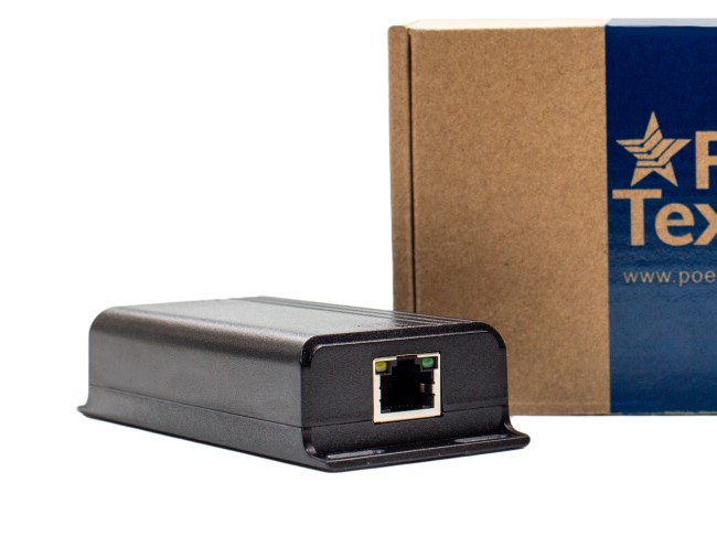
DENT-LK-C

DENT-LK-C

Home » Page 13

DENT-LK-C Installation and Configuration Manual


Welcome to the PoE Texas Manual for the DENT-LK-C line of products!

The purpose of the manual is to help you quickly and effectively install and configure your new DENT-LK-C kit.

Our goal is to make our products as intuitive and simple to use as possible, so we value your feedback and questions directly to us at service@poetexas.com.  Phone +1-512-479-0317.

Or you’re always welcome to leave questions or comments on our product pages: DENT-LK-C.

What’s Inside

PARTS LIST: DENT-LK-C2-A

  • Qty 1 DENT-LINC-CC
  • Qty 1 GPOE-1AB-56V60W
  • Qty 1 DENT-WS-S4
  • Qty 2 LTG-FP-2-2-4K


    PARTS LIST: DENT-LK-C2-B

      • Qty 1 DENT-LINC-CC
      • Qty 1 GPOE-1AB-56V60W
      • Qty 1 DENT-WS-S4
      • Qty 2 DWN-4-RDG-WH


      PARTS LIST: DENT-LK-C4-A

        • Qty 1 DENT-LINC-CC
        • Qty 1 GPOE-1AB-56V60W
        • Qty 1 DENT-WS-S4
        • Qty 2 LTG-FP-2-2-4K
        • Qty 2 DWN-4-RDG-WH


      PARTS LIST: DENT-LK-C4-B

        • Qty 1 DENT-LINC-CC
        • Qty 1 GPOE-1AB-56V60W
        • Qty 1 DENT-WS-S4
        • Qty 4 LTG-FP-2-2-4K


      Accessories and Tools

      Not Included in Base Kit

      REQUIRED ACCESSORIES:

      • Cat6 Ethernet  (2 cables length < 100m)
      • Single Gang JBOX or low voltage wall ring
      • 18-2 AWG wire (to each fixture)
      • 18-6 AWG wire (for wall switch)
      • WAGO wire connectors (~ 25)
      • Wire strippers


      OPTIONAL ACCESSORIES

      • PoE Tester (highly recommended )
      • 2ft Tbar (needed if putting into a 2ft x 4ft tile)
      • PoE / Data Switch if future networking is desired


      RECOMMENDED TOOLS

      • Wire strippers
      • Drill bits
      • Levels
      • Sheetrock saw
      • Wire cutters
      • Box cutter
      • Screwdrivers/Impact Drill
      • Wire Fishing tools
      • Carpenters Tape


      WIRING INSTRUCTIONS


      Download the Kit Drawing Set

      Kit Includes

      2x 2×2 Fixtures

      4 Button Light Switch

      100-200 Sqft Space

      Kit Includes

      2x 4″ Down Lights

      4 Button Light Switch

      100-200 Sqft Space

      Kit Includes

      2x 2×2 Fixture

      2x 4″ Down Lights

      4 Button Light Switch

      200-300 Sqft Space

      Kit Includes

      4x 2×2 Fixture

      4 Button Light Switch

      200-400 Sqft Space

      Watch a Professional Wire the Different Fixtures

      4″ Down Light

      4 Button Light Switch

      2×2 Troffer Light

      DENT-LINC

      MOUNTING INSTRUCTIONS


      • Cut the light switch mounting location and mount the low voltage ring
      • Determine where you plan to mount the DENT-LINC
        • You can mount the LINC in a ceiling or in an IDF or server room
        • It should be no more than 100 m (330 ft) from the supplied injector or a PoE++ (IEEE 802.3bt Type 4) switch
        • It should also be no more than 30 m (100 ft) from the furthest light switch or light fixture
      • Run the 18-6 wire from the wall switch location back to the LINC
      • Mount the light fixtures
      • Rough in the 18-2 wire from the LINC the light fixtures
      • Terminate the light fixtures and the LINC
      • Wire and terminate the light switch
      • Mount the light switch
      • Select where you will mount your injector or the IEEE 802.3bt switch
      • Mount the injector and power supply
      • Run the CAT 5e or CAT 6 cable from the LINC to the injector or switch
      • Terminate the CAT cable on both ends
      • Plug in the injector to power it on – confirm with the green lights
      • Connect the LINC to the injector or switch using the CAT cable
      • Your lights should come on immediately
        • If the lights do not come on immediately
        • Disconnect the CAT cable from the LINC
        • Double check you have terminated the lights to the LINC properly
        • Reconnect the CAT cable to the LINC

      As a safety precaution the LINC will not power up any output or input NOT terminated correctly.  You may need to simply unplug and plug the CAT cable in after you have properly terminated the wire whip on the light side of the LINC.

      Now you’re ready for programming.  Just kidding, check the next section on using the lights.

      PROGRAMMING AND CONFIGURATION


      Your LINC device comes pre-programmed so it is plug and play with these features.  Simply start using the buttons to control the lights.  See the image.

      You can re-program the LINC in the field by connecting the COR-TAP-Lite to a LAN with the LINC you’re interested in reprogramming.  Reprogramming does requires:

      1. COR-TAP-Lite (a PoE powered device)
      2. Local Area Network (LAN)
      3. DHCP Server (Usually a router or modem in smaller installations that hands out IP addresses)

      We recommend you contact us directly to arrange training on how to reprogram the LINC.

      Technical Specifications

      If you find this learning center helpful, like and subscribe on your social channels to learn when we post new guides!

      DENT-TAB-8-LED and DENT-TAB-10-LED

      DENT-TAB-8-LED and DENT-TAB-10-LED

      Home » Page 13

      DENT-TAB 8 and 10 LED Configuration Manual


      Welcome to the PoE Texas Manual for the DENT-TAB-8 and DENT-TAB-10!

      The purpose of the manual is to help you quickly and effectively navigate the configuration and installation of your new DENT-TAB.

      Our goal is to make our products as intuitive and simple to use as possible, so we value your feedback and questions directly to us at service@poetexas.com.  Phone +1-512-479-0317.

      Or you’re always welcome to leave questions or comments on our product pages: DENT-TAB-10.

      DENT-TAB-10-LED

      Product highlight featuring our DENT-TAB-10-LED Room Scheduler.

      DENT-TAB-8-LED

      Product highlight featuring our DENT-TAB-8-LED Room Scheduler.

      How to Flush Mount the Tab 8 LED

      Here is a quick tutorial on how to flush mount our DENT-TAB-8-LED

      What’s Inside

      PARTS LIST: DENT-TAB-10-LED

      • 1 X 10″ PoE Enabled Display
      • 1 X Wall/VESA Mount Bracket
      • 1 X Side Mullion Mount Adapter
      • 1 X  Package Wall Anchors
      • 1 X Power Adapter (Not required if using PoE)


      PARTS LIST: DENT-TAB-8-LED

      • 1 X 8″ PoE Enabled Display
      • 1 X Wall/VESA Mount Bracket
      • 1 X Side Mullion Mount Adapter
      • 1 X  Package Wall Anchors
      • 1 X Power Adapter (Not required if using PoE)
      • 4 X screws and dry-wall anchors


      CONFIGURATION

      Pre-Configuring Your DENT-TAB

      We have found it works best to pre-configure your TAB 8 and 10 prior to installation to make the install process faster and easier.  What does “pre-configure” mean?

      In this case, a device like the TAB8 and TAB 10 is best controlled by a Mobile Device Manager software, or MDM, which will upload the Denton DBI controller app and secure the device from operating any other software including other browsers.

      If  you’re new to MDM’s, have no fear.  PoE Texas can offer up to three TAB-8 or TAB-10 devices pre-configured on the PoE Texas MDM for you to test and become familiar with how the system works.  Then, you can upgrade to your own MDM account or system.  Your PoE Texas expert will be happy to help consult with you to find the right MDM to fit your needs and support you in configuring the TAB-8 or TAB-10 using your MDM.

      success@poetexas.com

      512-479-0317

        Ready to learn more about how to design and configure your ControlPortal as well as set up an MDM with profiles for your DENT-TAB?  Visit our

        ControlPortal Manual

        MOUNTING INSTRUCTIONS


        Ensure that you’re connected to the same Local Area Network (LAN) as the Primary Gateway COR-TAP to be able to present your ControlPortal.  Not sure what all that means?  Check out our manual on

        ControlPortal

        Technical Specifications

        Product Specifications

        CPU 8 Core ARM Cortex A7 CPU, 1.2Ghz
        Data Rate 10/100 Mbps
        Dimensions 72mm x 70 mm x 10mm
        Display Type 10.1 IPS Display, Resolution 1280×800, Brightness:350 nit, Capacitive Touch (5 point)
        Flash 8 Gb
        Input voltage 12 Volt/1500mA
        Installation Wall-Mount
        Max Power for Kit 12 watts
        Mount Type Wall-Mount
        PoE Standard IEEE 802.3af PoE
        Standard and Protocols H.264 2160p video decoding,
        Multi-format FHD video decoding, including Mpeg1/2, Mpeg4 SP/ASP GMC, H.263, H.264, VP6/8, AVS jizun, Jpeg/Mjpeg,etc.
        H.264 High Profile 1080p@30fps or 720@60fps encoding
        3840 x 1080@30fps 3D decoding, BD/SBS/TAB/FP supported
        Complies with RTSP, HTTP, HLS, RTMP, MMS streaming media protocols

        If you find this learning center helpful, like and subscribe on your social channels to learn when we post new guides!

        AT-1-52v30w; PT-GPOE-1B48v15w

        AT-1-52v30w; PT-GPOE-1B48v15w

        Home » Page 13

        Welcome to the PoE Texas Manual for the AT-1-52v30w  and PT-GPOE-1B-48v15w 

        The purpose of the manual is to help you quickly and effectively navigate the installation and functions of your new Power Over Ethernet Midspan for PoE+ and IEEE 802.3at compliant device.

        Our goal is to make our products as intuitive and simple to use as possible, so we value your feedback and questions directly to us at service@poetexas.com.  Phone +1-512-479-0317.

        Or you’re always welcome to leave questions or comments on our product pages: AT-1-52v30w. PT-GPOE-1B-48v15w 

        What’s Inside

        AT-1-52v30w

        PARTS LIST:

        • 1 X Midspan Injector
        • 1 X AC Cable Adapter


        Additional items you’ll need not included:

        Patch cables to the switch and home run cables to the device


        PT-GPOE-1B-48V15W

        PARTS LIST:

        • 1 X Midspan Injector
        • 1 X AC Cable Adapter


        Additional items you’ll need not included:

        Patch cables to the switch and home run cables to the device


        General Installation

        A midspan like the AT-1-52v30w is a simple device to add on to a network port, and the purpose is to add PoE+ to any network or PoE switch.

         With this in-line device, simply connect any networking or PoE switch you need to add PoE+ to.  Using a short Ethernet patch cable from the switch’s data port to the LAN port on the PoE midspan.   Then the POE port adjacent to the LAN port will now have that IEEE 802.3at (30 watts) power budget and up to gigabit pass through data.  Finally, connect the AC power cable to a 120/240 VAC 50/60 Hz outlet.

        This device has grounded ports.  Not sure what grounding is?  Panduit has some great graphics around grounding.

        CONFIGURATION

        There is no configuration necessary with this device.  Simply plug it in.

        The green LED indicates power on.  If the green light begins to blink at any time, it could indicate there is a short in the circuit or a compatibility issue.


        STEPS TO TROUBLESHOOT:

        1 – At the injector, disconnect the PoE port from your device.  Use a PoE Tester to confirm the device is able to power on using a short jumper cable.

        2 – At the other end of the network cable to your device, disconnect the device and use the PoE Tester to confirm it is able to negotiate PoE.

        3 – Connect the PoE Tester to the end device to monitor power consumption.


        If you’re able to power on the device with the PoE Tester inline, it’s likely a compatibility issue.  Please contact us at service@poetexas.com to find you the right solution.

        Technical Specifications

        AT-1-52v30w

        Product Specifications

        AC Plug Connector Type IEC C6 – Cable Included
        Adapter length 3 ft
        Certifications CE/FCC
        Data + PoE Ports 1
        Data Ports 1
        Data Rate Gigabit
        Dimensions 10.5 cm x 5.5 cm x 3.4 cm
        Input Frequency Range 50/60 Hz
        Input Voltage Range 100 – 240VAC
        LEDs Per Port 2 (PoE Port)
        Max Power for Kit 32 Watts
        Max. Amps Per Port 580 mA
        Operating Humidity 20% – 80% Non-Condensing
        Operating Temperature Range 0 – 40 C
        Output Voltage 52 Volts
        PoE Method IEEE 802.3at
        PoE Mode/Pinout Mode B (+4,5 / -7,8)
        PoE Standards Supported 802.3at
        Storage Temperature -20C – 70C

        PT-GPOE-1B-48V15W

        Product Specifications

        Certifications CE/FCC
        Data + PoE Ports 1
        Data Ports 1
        Data Rate Gigabit
        Input Voltage Range 100 - 240VAC
        LEDs Per Port 2 (PoE Port)
        Max Power for Kit 15 Watts
        Max. Amps Per Port 320mA
        Operating Humidity 20% - 80% Non-Condensing
        Operating Temperature Range 0 - 40 C
        Output Voltage 48 Volts
        PoE Method Passive
        PoE Mode/Pinout Mode B (+4,5 / -7,8)
        PoE Standards Supported 802.3af
        Storage Temperature -20C - 70C

        If you find this learning center helpful, like and subscribe on your social channels to learn when we post new guides!

        ControlPortal

        ControlPortal

        Home » Page 13

        ControlPortal

        Welcome to the PoE Texas Manual for our ControlPortal!

        The purpose of the manual is to help you quickly and effectively navigate the creation, installation, and functions of your new ControlPortal.

        Our goal is to make our products as intuitive and simple to use as possible, so we value your feedback and questions directly to us at service@poetexas.com. Phone +1-512-479-0317

        Privacy Policy

        Do you need convenient Room Scheduling?

        Check out our MeetingPortal app

        For easier and high visibility office scheduling, check out our PoE Tablets with our MeetingPortal app.

        Click Here

        Prerequisites

         EQUIPMENT REQUIRED:

        The exact amount required depends on the project’s size

        • COR-TAP GATEWAYS

          • At least one for Primary ControlPortal Gateway
          • Any number of Secondary gateways (can act as backup Primary)
        • ControlPortal- COMPATIBLE DEVICES

          • TAB-10

            • Includes an LED Ring Features, Alarms, and Kiosk Mode (requires MDM provisioning for Kiosk)
          • Android Tablet- Any device with Android 8.0 or higher

          • iPad

            • Support for iOS is in beta development and will be available soon for full deployment
          • PC’s and Other Displays:

            • Mac/iOS devices with Safari Browser
            • Windows devices with Chrome Browser
            • Linux devices with Chromium Browser
            • Chrome OS device

        Features

        Current supported features you’ll want to know about:

        MDM Provisioning

        (NOT REQUIRED for non-kiosk devices)

        Before you start:

        Android, iOS, and other devices require an MDM system operate in true kiosk mode.  We also recommend an MDM because you can control the devices’ profiles, distribute applications, configure system settings, remotely connect for assistance (on-premise permission required), track their status (battery, geolocation, etc.), and prevent any sort of tampering including in an event of physical theft.

        If you need an MDM account set up and don’t already have an MDM, you can refer to our MDM Initialization Instructions to learn about a system we recommend.  If you require assistance or have any other questions about an MDM please contact our customer success team.

        Device Provisioning

        To provision an MDM Device please accurately follow the steps described in Chapter 4 of the MDM Initialization Instructions or speak to your MDM service provider.

        Enabling ControlPortal (at Primary ControlPortal Gateway)

        When you’re ready to create your first ControlPortal page, you will need to enable the ControlPortal for the LAN. Then the ControlPortal can be accessed manually using http://wallstation.local/ (only works for client devices on the same LAN) or will be opened automatically if you are using our ControlPortal app (has to be on the same LAN).

        STEPS:

        1. Decide which gateway you are going to make the Primary ControlPortal Gateway. It is a good idea to choose the gateway that is the least likely to undergo any network or structural changes, be offline, or be decommissioned in the future.  If you have enough ControlPortal , we would recommend choosing one ControlPortal as your “ControlPortal ” server.
        2. Visit that gateway’s “Config” page (1).
        3. In the “General Settings” (2) section check the “ControlPortal V2 Primary” checkbox (3). Wait 10 seconds and refresh the page. If the checkbox stays checked it means the activation was successful. If the checkbox isn’t checked please make sure no other Primary ControlPortal Gateway is present on the network or contact our customer support.

        Adding Rooms and Adding Objects to Rooms

        Next let’s create a Room entity, which is what a ControlPortal will present as a page.  By this point, you should already have all the necessary objects, groups, and sensors created. You can refer to the COR-TAP Gateway documentation for more information.

        STEPS:

        1. Navigate to the “Rooms” page of your Primary ControlPortal Gateway
        2. Click the “New” button
        3. Fill in the parameters of your new Room
          • Support Phone and Support Email will be shown and used for the generation of the QR codes in the “Service Contacts” menu.   You can add your own information here.
          • To learn more about Order Locking, please refer to the corresponding chapter
          • To learn more about Service PIN, please refer to the corresponding chapter
          • In the Associated Schedule field, you can choose the gateway the schedule from which will be shown on the Room’s ControlPortal screen
          • Occupancy Sound is the sound that will be played on the Room’s occupancy sensor going into the “occupied” state
          • Custom background is a JPEG image of compatible dimensions (please make sure the dimensions are compatible with the screen, the image will be stretched to attempt to cover both of the sides fully while keeping its aspect ratio, please keep in mind that control elements cover parts of the background).
            Make sure you have the right to use the image.
            You can find free-to-use high-quality background images with a color filter here:
            https://www.pexels.com/search/background/ (100K+ images)
            https://pixabay.com/images/search/background/ (100K+ images)
        4. Click “Ok”
        5. You can now drag and drop the devices you want to be commissioned to that room

        Accessing ControlPortal

        1. If you are using an MDM pre-configured Kiosk ControlPortal device it should connect to the Primary ControlPortal Gateway automatically as long as it is on the same LAN and the valid MDM kiosk policy is present (please refer to MDM Initialization Instructions or contact our customer support if you need to get an MDM system set up).
        2. If you are using an Android Device that is not Kiosk you can access ControlPortal by installing our ControlPortal Android App
        3. If you are using a device that supports mDNS/Bonjour name resolution (e.g. all Apple products, Windows 10 Build 1511+, some Linux distributions, etc.) you can use http://wallstation.local/ in Chrome or Safari browser to access ControlPortal on the same LAN.
          • If you are connected to the COR-TAP’s Wi-Fi hotspot use http://wallstationwifi.local/ instead
        4. If you have a device that doesn’t support mDNS/Bonjour, use http://<primary-gateway-name> (where <primary-gateway-name> is the hostname of your Primary ControlPortal Gateway which you can find in your gateway settings, make sure to replace underscores (_) with dashes (-) if there are any underscores present)

        Single-room Mode

        By default, all ControlPortal clients have access to all Rooms. To limit a client device to a single Room use one of the next methods:

        1. Switch to another Room different from the Room you want to lock the device in and open the Room Selection Menu by tapping the Room’s name. In that menu tap and hold the target Room’s button until the screen is refreshed. The Single-room Mode will now be active.
        2. Alternatively, you can use http://wallstation.local/<room_name> to enter the Single-room Mode via URL.

        To exit the Single-room Mode tap the “Disable single-room mode” button in the Service Menu. Please refer to the “Service Menu” chapter for information on how to access it.

        To activate:

        To disable:

        Pinning and order locking

        To control the order of Scenes and Devices on the screen you can use next features:
        1. Pinning – by tapping on and holding a Scene or a Device button you can pin it at the top of the corresponding list. Pinned objects are indicated with a star added to their name. Each new pinned object always goes on top of its pinned list, that way you can control the order of the list of the pinned objects by pinning target objects in the desired order.
          To unpin an object tap and hold the target object’s button the same way as you did for pinning it.
        2. Objects from the “More” menu that were recently used go to the top of the corresponding object list after the pinned objects (if there are any). This ensures that devices that are being used frequently are more likely to be on the main object list.
        3. Order locking which you can find in the settings of the Room allows you to disable both Pinning and “More” menu auto-sorting features.  In that case, you can control the order of the objects by adding them to the room in the order you want them to be on the ControlPortal screen. The ControlPortal user will not be able to change the order of the objects from their ControlPortal screen.

        Scene-only (Portrait) Mode

        If the device screen is too small to effectively display the full version of ControlPortal or you just need it to only display Scenes you can rotate the device that supports orientation change into portrait orientation.

        Alternatively, if available, you can make the ControlPortal window height greater than its width which will also enable Portrait Mode.

        Gateway-issued commands

        In the “Control Commands” subsection of the “General settings” section of the Primary ControlPortal Gateway’s page you can issues next commands:

        1. Override screen brightness value for all ControlPortal
        2. Reload all ControlPortal (refreshes their browser page, if the device is reachable)

        LED Ring Features

        Only available on Denton LED Ring-enabled devices

        1. Automatic accent color will be calculated from the background image and applied automatically on any background change.
        2. Manual LED Ring overrides are available from the Service Menu (please refer to the Service Menu chapter on how to access it) and will allow you to override both the color and the on/off state of the LED Ring.

        Service Menu

        Service Menu is a menu that contains Service Controls meant to be only available to authorized personnel.

        To access this menu you have to set up the Service PIN in the settings of the Room. Please note, that Service PIN is per-Room, meaning you can access the service menu from that Room only if you know the PIN for that Room. That allows you to have flexible access zones with separated access levels. Please refer to the “Adding Rooms” chapter for more information on setting up a Room.

        After the PIN is set up you can access the service menu by opening the “Service Contacts” menu and tapping and holding the text line that contains the ControlPortal IP (1), tapping on the white field that will appear below it (2), entering the PIN correct for the selected Room in the number pad (3), and tapping the blue button (4).

        Please refer to the list of features to see what features you can control from the Service Menu.


        1. If the ControlPortal main screen appears, but you don’t see any controls
          • If you use a 3rd party router your router may lack the support of DHCP DDNS (which generally means it may be undertiered for the purpose of being your building automation router) or you have DNS resolution misconfigured:
            If DHCP DDNS doesn’t work on your LAN you should aim to fix your network DNS resolution, you can contact our technical support which will provide you with further steps.
            Alternatively, you can try to use the MultiVerse network map fallback, by going to the “General Settings” and unchecking “ControlPortal use DHCP DDNS”, but it is not recommended as a permanent solution (as faulty DHCP DDNS often indicates other issues on the network) and is not guaranteed to resolve the issue. It also depends on network multicast working properly.
          • There are other potential network and configuration issues that may lead to that general symptom, as it basically indicates that the ControlPortal web app itself was delivered to the client device, but the delivered app couldn’t initialize the configuration and controls. Please contact our customer support for further diagnostics.
        2. ControlPortal doesn’t load at all
          • Please check your network status and direct LAN reachability of the Primary ControlPortal Gateway. It often means that either the client device is offline, or that the Primary ControlPortal Gateway is offline.
          • Your router or network may have issues with multicast and mDNS. In that case please contact our customer support.
        3. ControlPortal screen restarts (blinks) and doesn’t stop
          • There are some issues with your network or configuration that ControlPortal could not resolve automatically, please contact customer support.
        4. Alarms stop working after the screen goes to sleep
          • If you are running ControlPortal Android App make sure it is added to the battery optimization exceptions. That is dealt with natively in Denton devices.
          • For other devices and operating systems make sure the device doesn’t go to sleep or puts the app to sleep. For example, your native phone call app and alarm clock are only able to immediately deliver you a call and wake you up on time because they are system apps that are added to the battery optimization exceptions by default. Due to mobile operating system policies 3rd party apps are not allowed to acquire those permissions (as well as most other permissions) automatically.
        5. Some controls are unavailable
          • If you can’t use some control you’ve been able to use previously it may mean that the gateway that provides those controls is currently offline. Please check the connection and contact customer support if you are unable to resolve the issue.

        If you find this learning center helpful, like and subscribe on your social channels to learn when we post new guides!

        GBTS-10-8-M Rev 2

        GBTS-10-8-M Rev 2

        Home » Page 13

        Welcome to the PoE Texas Manual for the GBTS-10-8-M-V2!

        The purpose of the manual is to help you quickly and effectively navigate the installation and functions of your new 8 port IEEE 802.3bt PoE switch designed for Intelligent Lighting and Automation distributed networks. 

        Our goal is to make our products as intuitive and simple to use as possible.  We value your feedback and questions.  You can reach us directly at service@poetexas.com and +1-512-479-0317.

        Or you’re always welcome to leave questions or comments on our product pages: GBTS-10-8-M-V2

        Note: Installation and servicing should be performed by qualified personnel.

        IMPORTANT SAFEGUARDS
        1. READ AND FOLLOW ALL SAFETY INSTRUCTIONS.  SAVE THESE INSTRUCTIONS.
        2. Do not use outdoors.
        3. Do not let power supply cords touch hot surfaces.
        4. Do not mount near gas or electric heaters.
        5. The grounding screw is for signal integrity and not for branch safety circuit grounding.
        6. Equipment should be mounted in locations, such as Intermediate Distribution Frames (IDF’s), behind locked doors.
        7. The use of equipment including interconnecting wiring not recommended by the manufacturer may cause an unsafe condition.
        8. Do not use this equipment for other than inteded use.

        SAVE THESE INSTRUCTIONS.

        What’s Inside

        PARTS LIST:GBTS-10-8-M-V2

        • 1 X PoE Switch
        • 1 X Wall Mount Kit
        • 1 X DIN rail Mount Kit – Does not include DIN rail
        • 1 X DC Power Connector
        • 1 X Relay Power Connector

        NOTE: The switch is not Plenum rated per se so PoE Texas kit the switch in a NEMA rated enclosure for mounting in plenum spaces or areas not secured behind a locked door.

        GENERAL INSTALLATION


        To deploy your new IEEE 802.3bt DC powered switch, you really only need three key things:

        1. DC power – 42-58 Volts DC, though we recommend 53 volts or higher for Lighting and Automation projects.
        2. Gigabit Uplink Data on the Small Form-Factor Pluggable Fibers slot
        3. Space:
        • Wall Mounted: 6.75″ x  4.5″ (included wall mounting brackets)
        • DIN Rail: 6.5″ x 3.5″ (included DIN rail bracket)
        • NEMA Enclosure: 12″ x 10″ x 6″ (Enclosure Accessory)

        Mounting hardware like screws or wall anchors not included.

        Key note:

        • Per UL/IEC 62368-1 Clause F.4, this equipment is intended for use only in a restricted access area.

        That’s it!  Let’s get it mounted, then discuss how to configure it.  

        About the Power Supply

        The GBTS-10-8-M is designed to take 48-58 volt DC power.  You’ll notice there are two (V1-V2) input power points on the side. Additionally, there is an In (-) and In (+). When wired to the DENT-LINC as an input it can be used for brownout detection (see diagrams below). 

        For One Power Supply (PS) with two outputs: Diagram  

        Connect
        PS V1+ to Switch Input V1+
        PS V1- to Switch Input V1-
        PS V2+ to Switch Input V2+
        PS V2- to Switch Input V2-


        For One Power Supply (PS) with one output: Diagram

        Connect
        PS V1+ to Switch Input V1+
        PS V1- to Switch Input V1-
        PS V1+ to Switch Input V2+
        PS V1- to Switch Input V2-


        For Two Power Supplies (PS) with two outputs (Note: If using two power supplies, please balance the voltage): Diagram 

        Connect
        PS1 V1+ to Switch Input V1+
        PS1 V1- to Switch Input V1-
        PS2 V1+ to Switch Input V2+
        PS2 V1- to Switch Input V2-


        These screw down terminal sockets have are rated for 14 AWG wire.  We recommend crimp on ferrules to make inserting and removing the cable easier.

        The PS-53v3000w power supply designed to operate with this switch comes with interconnecting cables.  You can calculate the correct cable gauge for  your application at the correct distance using our Voltage Drop Calculator.

        If you have questions about how to wire your switch, you can speak to PoE Texas about your cable needs for your project. Additionally, we have installation examples here.

        CONFIGURATION

        The GBTS-10-8-M will function perfectly as a basic IEEE 802.3bt switch for PoE lighting and automation without any configuring right out of the box.  For most basic networks, you do not need to configure the switch to operate.  It will power on, negotiate the 4 Pair PoE for automation, and forward on the right network traffic for a basic configuration.

        However, if you need to configure the switch, you will need a fundamental understanding of networking to do more than a few key management items.  We won’t try to show you how to do all the possible Layer 2 configurations in this manual.  Please contact us if you’d like additional information on configuring Layer 2 settings.

        We will cover some important features you can control such as turning on a PoE watchdog, monitoring the ports, and setting your IP address to match your network.

          CONFIGURATION GUIDE

          Generally, the device comes pre-configured for optimal performance, however, PoE Texas recommends these settings be adjusted:

          • Password – change the password from the default setting
          • Set date/time
          • Name the device per the project nomenclature for identification
          • Optional: Configure VLANs

            Configuration Guide for Emergency Lighting (UL924)

            (PENDING) This PoE switch can be configured for service as a power distribution device for emergency lighting in compliance with UL924.  In order to configure this device for service as an emergency lighting power distribution device, you need to configure it with these parameters in mind:

            • The emergency lightin system must includea UPS backup sized sufficiently so the PoE switch remains powered on during the transfer time from normal to emergency power

            • The PoE switch does not locally store emergency power, so a UL924 rated power transfer and storage device or UL rated back up generator must be provided for 90 minutes of emergency lighting power

            • When used in a UL924 configuration, this PoE switch does not do load shedding so all loads, or lights, connected to that switch must be emergency lights

            • This PoE switch acts simply as a power distribution panel that accepts power from an upstream UL924 transfer device and power storage system and distributes it to downstream lights

            For detailed wiring and configuration information for Emergency Lighting, please see the diagrams below.


            Configuration Guide Option 1

            Configuration Guide Option 2

            Configuration Guide for Power Supply PS-53V3000W

            Generally, the device comes pre-configured for optimal performance, however, PoE Texas recommends these settings be adjusted:

            • IP address – the device does not allow for DHCP clients, so a subnet or VLAN should be defined in advance
            • Password – change the password from the default setting
            • Set the date and time
            • Name the device per the project nomenclature for identification
            • Enable/disable batteries as necessary – enable batteries only if one is connected
            • Install and configure temperature probes


            Web Management

            CONNECTING TO THE CONSOLE

            The GBTS-28-24-M has a web-based management interface that can be accessed through any of the network ports on the switch.  Before you integrate it into your network, you will need to set the IP address to match your local network settings.

            To start the configuration you need directly connect a network port to a computer.  If you don’t have an ethernet port on your laptop, this works just fine with an ethernet to USB adapter.

            Then power on the injector using any 48-56 volt power supply.  The settings will remain in the device even if you power it off and power it on again.

            Now comes the techiest part of the process.  You will need to disconnect your computer from wifi and the internet.  I know this feels very dangerous, but it’s only for a moment.

            We show the instructions in the video to the left for a Windows computer.  If you need help doing this on a MAC, simply go to YouTube and search on setting an fixed IP address for a MAC.  Then use the IP address information I give below.

            In Windows, navigate to your Network and Sharing Center.  If you don’t know how to get there, simply click on the Window button on the bottom left and type “Network and Sharing Center”.

            When it comes up, you should see an ethernet connection.  If not, double check 1) you’re connected to the switch through an ethernet port, and 2) the switch is powered on.  Click on the ethernet connection.  It will bring up a dialog box.Click “Properties” on the bottom left.

            In the next dialog box, look in the middle for “Internet Protocol Version 4”.  Click on it, then click “Properties” in the bottom right.

            Fill out the fields just like this.

            Click: User the following IP address

            IP Address: 192.168.0.10

            Subnet Mask: Sets itself

            Default Gateway: 192.168.0.5


            Preferred DNS Server: 8.8.8.8

            Alternate DNS Server: 4.2.2.2

            Hit Okay to close this dialog, then Okay one more time.

            I’ve tried not hitting okay the second time, and I couldn’t get it to connect.  So, make sure it hit okay to close out the two dialogs.

            Finally, open a web browser and type 192.168.0.1 in the URL Bar.

            The default username is: admin

            The default password is: admin

            You’re in!

            Configuration Settings

            As mentioned above, we’re not going to try to show you how to use all of the functions of a Layer 2 switch, in good part because most of the functions do not really apply to Automation and Lighting.  The video configuration guide shows you how to:

            • Quickly see the status of the ports
            • Log on to the switch
            • Change the basic configurations in terms of time, location, etc.
            • Add or change users
            • Enable/Disable communication to the switch
            • Set the time clock to a server
            • Create a backup configuration file
            • Change the basic IP address of the switch
            • Manage the PoE including setting the total power budget
            • Finally, set a PoE port watchdog to reboot any ports that lose communication

            Technical Specifications

            Product Specifications

            Buffer 4Mbit
            Certifications CE, CB, PFC
            Connector Types Screw In – 20 amp max per connector
            Dimensions 163.2mm×110mm×65.8mm
            Downlink Ports 8*10/100/1000Base-T (PoE)
            ESD Immunity 6KV: Contact discharge 15KV: Air discharge Execute: IEC61000-4-2
            Input Voltage 12-58 VDC
            IP Grade IP40
            Jumbo Frame 10K bytes
            LED Indicator 8*Link/Act (Green), 8*PoE (Orange), 1*PWR (Red)
            MAC Address Table 16K
            Operating Humidity 5%-95% (Non-condensing)
            Operating Temperature -10-55℃
            Packet Forwarding Rate 14.9Mpps
            PoE Line Pair 1/2/4/5(+),3/6/7/8(-)
            PoE Output Power PoE output power for singe port≤90W, Total PoE power budget≤720W
            PoE Standard 802.3af/at/bt(PSE)
            Power Output 0-10 A, 37-56 VDC, 720 watts
            Standard and Protocols IEEE802.3 , IEEE802.3u, IEEE802.3ab, IEEE802.3Z, IEEE802.3X, IEEE 802.1D, IEEE 802.1af/ at/bt
            Storage Temperature -40-85℃
            Surge Immunity 6KV Execute: IEC61000-4-5
            Switching Capacity 20Gbps / non-blocking
            Uplink Ports 2*1000Base-X SFP Slots

            If you find this learning center helpful, like and subscribe on your social channels to learn when we post new guides!

            iOS Compatibility Table – Check Before You Update Your iPad

            iOS Compatibility Table – Check Before You Update Your iPad

            iOS Version Compatibility Table

            See if PoE Texas Has Identified Any iOS Compatibility Issues Before You Update

            Home » Page 13
            Does iOS Have Compatibility Issues?

            Occasionally we have found iOS updates have minor issues that most users wouldn’t notice.  However, based on hard won experience, if you need your device fully functional 24/7, we recommend disabling the automation software update setting on your device and choosing when to perform an update after PoE Texas has done compatibility testing.  See your product manual for how to adjust settings.

            Then, check here for our testing of the most recent versions of iPadOS to confirm whether we have found any compatibility issues with any particular versions.  Then you can choose when to push updates to your iPads to get the best, most reliable performance out of your devices.

            Don’t have time to keep coming back here regularly?  Subscribe to our update list where we will notify you of the results of our compatibility testing as new iOS versions come out.  Or contact us at any time.

            Subscribe

            success@poetexas.com or 512-479-0317

            * Compatible except device loses data connectivity during reboot and needs to be restarted to reconnect.

            Subscribe to Get Notified by Email as iOS Updates Happen

            GATS-6-4-52v65w

            GATS-6-4-52v65w

            Home » Page 13

            Welcome to the PoE Texas Manual for the GATS-6-4-52V65W!

            The purpose of the manual is to help you quickly and effectively navigate the installation and functions of your new GATS-6-4-52v65W. 

            Our goal is to make our products as intuitive and simple to use as possible, so we value your feedback and questions directly to us at service@poetexas.com.  Phone +1-512-479-0317.

            Or you’re always welcome to leave questions or comments on our product pages: GATS-6-4-52v65w.

            What’s Inside

            PARTS LIST:GATS-6-5-52v65w

            • 1 X PoE Switch
            • 1 X AC Cable
            • 1 X Manual

            You have everything you need to get your switch up and operating.  Let’s get started.


            GENERAL INSTALLATION


            To deploy your new PoE+ or IEEE 802.3at switch, you really only need three key things:

            1. AC power – 120 VAC 60 Hz or 220 VAC 50 Hz – 65 watts
            2. Gigabit Uplink Data on the RJ45 port
            3. Space: 8″ wide by 5″ long desk or wall space

            * Optional: If you’re wall mounting it, you do need screws and wall anchors.

            That’s it!  It’s designed to be a simply, cost effective PoE+ powered switch you can implement quickly.  You don’t need configuration cables, software downloads, apps, or certifications to use it!

             Your switch has four 10/100 PoE ports, two 10/100 Mbps data only ports, and LED indicator lights.  Not a lot to worry about here.  Let’s show you how it goes together.

            Put it together:

            DESK MOUNT:

            If you’re going to set this on a desk or a shelf, you simply place the switch into the location where you need it close enough to the outlet and network connection to your router or switch.

            WALL MOUNT:

            If you plan to mount this on a wall, simply use two wall screws 7.1″ apart to hang the switch on the wall.  You’ll need a small philips head screwdriver for this.

            Now you can plug it in using the included AC cable to power it up.  If you’re grounding your network*, you can use the earthing lug on the back of the switch.*  You might be tempted to overground your network.  Only ground your network in one location and ground it well.  Adding more than one grounding point could actually introduce noise to your network.

            Let’s power this thing on and configure it!

            CONFIGURATION

            Okay, you’re done configuring.  The switch will work right out of the box.

            You can choose to change the settings on all the ports by selecting VLAN, which will create virtual local area networks for each port so that port 1 will not communicate with port 2, etc. for a more secure network.  Or you can choose to “Extend” the range which will allow the PoE ports to communicate up to 10 Mbps up to 250 meters (820 ft).

              LED LIGHTS: All the fun blinky lights!

              What you really want to check for is that the LNK/ACT light is blinking properly.  The LED should blink green indicating communication is happening with your device.

              WIRING

              Technical Specifications

              Product Specifications

              AC Plug Connector Type C14
              Adapters included Yes
              Cable connector length 3 ft
              Certifications CE, FCC, RoHS
              Data + PoE Ports 4
              Data Ports 2 10/100 Mbps
              Data Rate 10/100 Mbps
              Dimensions 8″ x 5″ x 1.325″ in.
              Input Voltage Range 120 / 220 VAC
              LEDs Per Port 1 – PoE, Activity
              Max Power for Kit 65 watts
              Mount Type wall and desk
              Operating Humidity 10% to 90%
              Operating Temperature Range -20 – 50 C
              Output Voltage 52 volts
              PoE Method IEEE 802.3af; IEEE 802.3at
              PoE Mode/Pinout Mode A (-1,2 +3,6)
              PoE Standards Supported IEEE802.3, IEEE802.3u, IEEE802.3ab, IEEE802.3z, IEEE802.3az, IEEE802.3x IEEE802.3af, IEEE802.3at
              Storage Temperature -40-80 C

              If you find this learning center helpful, like and subscribe on your social channels to learn when we post new guides!

              AF-USBC

              AF-USBC

              Home » Page 13

              AF-USBC – IEEE 802.3af PoE to USB-C Splitter

              PoE to USB-C

              What’s Inside

              PARTS LIST: AF-USBC

              • 1 X POE SPLITTER

              The AF-USBC comes with a male USB-C connector and an RJ-45 Connector.

              General Installation

              Your new PoE splitter is designed to be simple to install and set up.  It is small and light enough to leave “inline” with your network cable.

              A adhesive or screw backed cable anchor is sufficient to hang the adapter on a wall or enclosure.

              Once it is in place, simply plug the end of your category cable into an IEEE 802.3af PoE or 48-56 volt passive Power Sourcing Equipment (PSE) with a data source (optional), and the other end into your device such as a camera, Raspberry Pi, Android tablet, or any compatible device.

              Please note that this device does not operate on the Power Delivery PD standard.  That means, for example, iPads, Nest Cameras, Samsung Tablets, etc will not necessarily negotiate power and charge.  Please test your device prior to use.  If you do need Power Delivery (PD) charging, you can see our full line of PD compatible devices:

              I Want Power and/or Data for my iPad Air, Samsung Tab, or a Power Delivery Device!

              Visit Our Full Line of Power Delivery Compatible Devices

              CONFIGURATION

              There is no configuration necessary with this device.  Simply plug it in.


              The yellow LED indicates power on the primary side (your PoE side).  The green indicates power on the secondary (5 volt side).

              Technical Specifications

              Product Specifications

              Cable connector length 8.5 inches
              Cable connectors RJ45 Male, USB-C Male
              Data + PoE Ports 1 (input)
              Data Ports 1
              Data Rate 10/100 Mbps
              Connector USB-C Male
              Dimensions 6x1x1.5 in.
              Input voltage 44 volts to 57 volts
              Max. Amps Per Port 2
              Operating Humidity 5% to 90%
              Operating Temperature Range -10 to 60°C
              Output Voltage 5 volts (no Power Delivery)
              PoE Method Active
              PoE Mode/Pinout Mode A (-1,2 +3,6)/Mode B (+4,5 -7,8)
              Power Input Female RJ45
              Weight 1 oz

              If you find this learning center helpful, like and subscribe on your social channels to learn when we post new guides!

              BT-USBC-A-PD

              BT-USBC-A-PD

              Home » Page 13

              BT-USBC-A-PD – The PoE Convert for USB-C Laptops and Tablets with a USB-A Port for Accessories

              Welcome to the PoE Texas Manual for the patent pending BT-USBC-A-PD that gives you wired Power and Data for your USB Type C laptop plus two USB-A ports for an additional accessories!

              The purpose of the manual is to help you quickly and effectively navigate the installation and functions of your new Power Over Ethernet Converter.

              Our goal is to make our products as intuitive and simple to use as possible, so we value your feedback and questions directly to us at service@poetexas.com.  Phone +1-512-479-0317.

              Or you’re always welcome to leave questions or comments on our product page: BT-USBC-A-PD

              What’s Inside

              PARTS LIST:

              • 1 X POE++ (IEEE 802.3bt Type 3 or Type 4) Converter

              Cable accesories sold separately.

              USB-C Cables

              You can choose one of our USB-C cables to fit your application length. Our USB-C to Lightning connector allows you to charge and send data to an iPad from our AT-USBC-A-PD.

              GENERAL INSTALLATION


              Your new PoE converter is designed to be simple to install and set up.  It has wings to allow the unit to be attached to a desk or wall..


              Once it is in place, simply follow these steps in order:

              1 – Plug the RJ-45 end into an IEEE 802.3bt PoE (POE++) or 48-56 volt 4Pair passive Power Sourcing Equipment (PSE) with a data source

              2 – Ensure the device you’re connecting to is on and logged in

              3 – Plug the USB-C connector into the device

              The converter will automatically set up the network connection with your device and begin charging.  To confirm that, go to the General settings tab or look for the <…> symbol next to Ethernet.

              * Please use the provided spacer clamp to avoid damage to the USB-C connector which will void the product warranty.

              CONFIGURATION

              Configuring Your BT-USBC-A-PD

              You’re not required to do any configuration with IEEE 802.3bt switches and injectors. The PoE++ to USBC converter will connect to the PoE switch, negotiate the USB-C power delivery profile, and begin transmitting data.   

              Not sure what kind of PoE your network switch provides?  You can use the LED’s on the side of the device to see what type of PoE power your switch has negotiated with the BT-USBC-A-PD.

              Some previous version Cisco uPoE switches do require some configuration on the switch to enable the right PoE for the BT-USBC-A-PD.

              Or here are the steps you take after you’ve logged into the terminal.

              Switch> enable
              Switch# configure terminal
              Switch(config)# interface gigabitethernet2/0/1

              Switch(config-if)# power inline port 2-event
              Switch(config-if)# end

              You can still set up your iPad to not automatically lock on a timer.  When the screen locks if you would like the screen always on.

              • Go to the Settings icon on your iPad
              • Select Display & Brightness
              • Select Auto Lock
              • Set the limit to Never


              The splitter will auto-configure the IP settings to default as soon as you connect it up including Dynamic IP addressing.

              1. Navigate to General Settings, then you’ll see a symbol for the LAN <…>
              2. Select this and you’ll see the option for PoE Texas LAN, select it

              You’ll see your IPV4 IP address information.  If it shows “Automatic”, that means your getting a dynamically assigned IP address.

              If you’d like to reconfigure the IP address, DNS, and HTTP Proxy settings, you can do that by selecting these options.  

              The most used option will be fixing your IP address by selecting the “Automatic” button.

              For the other networks settings, we’d recommend talking to a service provider or give us a call: 512-479-0317 or service@poetexas.com.

              Technical Specifications

              Product Specifications

              Adapters included USB-C to USB-C Right Angle Bi-directional cable
              Connector Types USB-C
              Data Rate (Input) 10/100/1000 Gigabit / (Output) 10/100 Mbps
              Data Standard USB 2.0 (Output)
              Input voltage 48-56V
              LEDs Per Port Green (POE) / Yellow (USB-C) / Blue (PoE Classification)
              Max Power for Kit 65 Watts
              Mount Type Wall or DIN rail (sold separately)
              Operating Humidity -10 – 60C
              PoE Method IEEE 802.3bt
              PoE Standard IEEE 802.3bt
              PoE Standards Supported USB-C PD
              Power Input 72 watts
              Power Output 5 volt 3 amp | 9 volt 3 amp | 12 volt 3 amp | 15 volt 2.6 amp | 20 volt 3.25 amp
              Weight 5 oz.

              If you find this learning center helpful, like and subscribe on your social channels to learn when we post new guides!

              AT-USBC-A-PD-MS

              AT-USBC-A-PD-MS

              Home » Page 13

              AT-USBC-A-PD-MS – The PoE Convert for USB-C Devices with a USB-A Port for Microsoft Surface Go

              Welcome to the PoE Texas Manual for the patent pending AT-USBC-A-PD that gives you wired Power and Data for your USB Type C devices plus a USB-A port for an additional device!

              The purpose of the manual is to help you quickly and effectively navigate the installation and functions of your new Power Over Ethernet Converter.

              Our goal is to make our products as intuitive and simple to use as possible, so we value your feedback and questions directly to us at service@poetexas.com.  Phone +1-512-479-0317.

              Or you’re always welcome to leave questions or comments on our product page: AT-USBC-A-PD

              Installing a Communify Kiosk?  Watch Our Videos on Proper Installation of the Devices

              Make sure to read the section on configuring your Cisco switch for 2 Event Classification.  Failure to configure the switch prior to connecting our device will void the warranty.

              What’s Inside

              PARTS LIST:

              • 1 X POE+ Converter
              • 1 X Startech DFS Certified Cable

              USB-C Cables

              You can choose one of our USB-C cables to fit your application length. Our USB-C to Lightning connector allows you to charge and send data to an iPad from our AT-USBC-A-PD.

              GENERAL INSTALLATION


              Your new PoE converter is designed to be simple to install and set up.  It is small and light enough to leave “inline” with your network cable.

              You may also choose to use the four M3 sized mounting brackets to secure the device to a wall or surface or mount it inside a wall using our In-wall wall bracket.


              Once it is in place, simply follow these steps in order:

              1 – Plug the RJ-45 end into an IEEE 802.3at PoE (POE+) or 48-56 volt passive Power Sourcing Equipment (PSE) with a data source

              2 – Ensure the device you’re connecting to is on and logged in

              3 – Plug the USB-C connector into the device

              The converter will automatically set up the network connection with your device and begin charging.  To confirm that, go to the General settings tab or look for the <…> symbol next to Ethernet.

              CONFIGURATION

              Configuring Your Cisco Enterprise POE Switch for 2 Event PoE Classification

              Yeah, I know that’s a mouthful.  Here’s the simple translation.  Cisco enterprise switches including the 9400 and 9300 models, which is a lot of them, come with a default setting that makes them less compatible PoE+ devices like the GAT-USBC-PD.   You’ll know the setting isn’t right because our device won’t power on correctly, and your device won’t charge.  How frustrating!

              It’s a simple enough fix.  You simply need to configure the ports that will power the GAT-USBC-PD to have 2 event classification.  You can find the Cisco documentation on how to do that here: CONFIGURE MY SWITCH

              Or here are the steps you take after you’ve logged into the terminal. 

              Switch> enable
              Switch# configure terminal
              Switch(config)# interface gigabitethernet2/0/1

              Switch(config-if)# power inline port 2-event
              Switch(config-if)# end

              How to Check for Power and Data in Kiosk Mode with the Communify app installed

              Once the kiosk has been connected to a properly configured PoE+ switch, powered on, and booted, you can simply swipe down from the top of the screen to view a status bar that will indicate whether the Surface Go is receiving power and charging as well as whether it has wireless or wired data connected. 

              Please contact your Communify representative if you do not see power and wired data.

              Do you need help with your Communify Meet or Greet Enclosure?

              See our assembly instructional videos below.

              Technical Specifications

              Product Specifications

              Connector Types USB-C with Power Delivery and Data | USB-A
              Data Rate (Input) 10/100/1000 Gigabit / (Output) 10/100 Mbps
              Data Standard USB 2.0 (Output)
              Input voltage 48-56V
              LEDs Per Port Green (Connection) / Yellow (Activity)
              Max Power for Kit 25 Watts total
              Mount Type Wall or DIN rail (sold separately)
              Operating Humidity -10 – 60C
              Output Voltage USB-C: 5V,2.6A; 9V,1.78A; 12V,1.34A; 15V,1.37A; 20V,1.15A
              USB-A: 5V 1A max
              PoE Method IEEE 802.3at
              PoE Standard IEEE 802.3at
              Weight 3 oz.

              If you find this learning center helpful, like and subscribe on your social channels to learn when we post new guides!