GAT-EXTENDER

GAT-EXTENDER

Home » ieee802.3at

GPOE-EXTENDER INSTALLATION MANUAL

Welcome to the PoE Texas Manual for the Extender Line of Products!

The purpose of the manual is to help you quickly and effectively navigate the installation and functions of your new Power Over Ethernet Extender.

Our goal is to make our products as intuitive and simple to use as possible, so we value your feedback and questions directly to us at success@poetexas.com.  Phone +1-512-479-0317.

Or you’re always welcome to leave questions or comments on our product page: GAT-Extender

If you’d like to learn more about our extender line to extend multiple devices on one network cable, check out these products: GBT-4-IW and GBT-4-60W.

What’s Inside

PARTS LIST: GAT-EXTENDER

  • 1 X Extender
  • 2 X IP67 glands [required use for proper install]

Key Features:

  • IEEE 802.3at and af compatible
  • 10/100/1000 Mbps Data Rate
  • IP67 rated for outdoor use; water resitant- DO NOT submerge in water [not water proof]

General Installation

Your new GAT-Extender is designed to be simple to install and set up. This unit is designed for indoor and outdoor use. If using outdoors, the unit is water resistant but not water proof, meaning the unit can withstand rain and snow but do NOT submerge the GAT-Extender in water or other liquids.

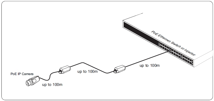
To install your GAT-Extender, place the extender inline after your PoE switch or injector (PSE) within a 100m (300 ft) distance from the PSE.  Using a second category cable to run to a second GAT-Extender or to your powered device within 100m. Please see the diagram below for distance placement.

To properly install the GAT-Extender the IP67 Glands MUST be used on the input and output side of the extender. Use scissors to cut through the gland and wrap the gland around the base of the category cable. Insert the gland into the GAT-Extender and cover with the metal protector by screwing on. This will assure your extender stays water resistant. For more detail on the install, please watch our youtube video below. Failure to properly install the glands with outdoor usage will lead to water leaks, voiding the warranty on the unit.

CONFIGURATION

There is no configuration necessary with this device.  Simply plug it in and follow the installation instructions.

OR Call a PoE expert for assistance +1(512)479-0317

Technical Specifications

Product Specifications

Certifications IEEE 802.3af (PoE), IEEE 802.3at (PoE+), RoHS Compliant
Data + PoE Ports 2
Data Rate 10/100/1000
Dimensions 209 mm x 53 mm x 37.5 mm
IP Rating IP67
Load Regulation
Max Power for Kit 30 Watts
Max. Amps Per Port 1.1Amp
Mount Type in-line
Operating Humidity 20%-80% Non-Condensing
Operating Temperature Range -40 to 65 C
Output Voltage 55v (Typical)
PoE Mode/Pinout Mode A
PoE Standard IEEE 802.3at
PoE Standards Supported IEEE 802.3af/at
Power Input 44 – 57 volts POE
Storage Temperature -40 to 85 C
Weight .80 lbs

If you find this learning center helpful, like and subscribe on your social channels to learn when we post new guides!

AT-LED-24V Driver and Light Kits

AT-LED-24V Driver and Light Kits

Home » ieee802.3at

AT-LED-24V Installation and Configuration Manual

Welcome to the PoE Texas Manual for the AT-LED-24V, AT-LED-24V-STRIP, AT-LED-24V-DISC, AT-LED-24V-BULB, AT-LED-24V-COB line of products!

The purpose of the manual is to help you quickly and effectively install and configure your new AT-LED-24V  kit.

Our goal is to make our products as intuitive and simple to use as possible, so we value your feedback and questions directly to us at service@poetexas.com.  Phone +1-512-479-0317.

Or you’re always welcome to leave questions or comments on our product pages: AT-LED-24V.

What’s Inside

PARTS LIST: AT-LED-DRIVER

  • AT-LED-24V PoE to LED driver
PARTS LIST: AT-LED-24V-STRIPS

  • AT-LED-24V PoE to LED Driver
  • 1 x AT-WS-1 Wireless wall switch
  • 1 x 2.2m 3200K LED Light Strip
PARTS LIST: AT-LED-24V-BULBS

  • AT-LED-24V PoE to LED Driver
  • 1 x AT-WS-1 Wireless wall switch
  • 3 x 2700K LED Light Bulbs
  • 2 x wire connectors
PARTS LIST: AT-LED-24V-DISC

  • AT-LED-24V PoE to LED Driver
  • 1 x AT-WS-1 Wireless wall switch
  • 2 x 6500K LED Disc Lights
  • 2 x wire connectors
Parts Lists: AT-LED-24V-COB

  • 1x RGB strip with remote
  • 1 x PoE+ driver
  • 1x wireless/battery-free light switch
  • Accessories and Tools

    Not Included in Base Kit

    REQUIRED ACCESSORIES:

    • Cat6 Ethernet  (2 cables length < 100m)
    • Single Gang JBOX or low voltage wall ring
    • Wire strippers

    DRAWING SETS

    Download the Kit Drawing Set

    Kit Includes
    1 x 24V LED driver

    1 x 2.2m 24V 3200K LED strip

    1 x Battery-free Wireless Toggle Light Switch

    500 Sqft Space

    Kit Includes
    1 x 24V LED driver

    2 x 6500K LED Disc lights

    1 x Battery-free Wireless Toggle Light Switch

    500 Sqft Space

    Kit Includes
    1 x 24V LED driver

    3 x 2700K LED BULBS

    1 x Battery-free Wireless Toggle Light Switch

    500 Sqft Space

    1 x AT-LED-24V

    1 x AT-WS-S1

    1 x RGB Strip

    1 x RGB Controller

    1 x RGB Remote

    MOUNTING INSTRUCTIONS

    • Before you mount anything, make sure you pair your light switch or multiple light switches with the AT-LED-24V driver.  See instructions here.
    • If mounting the light switch for flush mounting, identify the light switch mounting location and cut and mount a low voltage ring.
    • Otherwise, simply use the adhesive strip to mount the light switch on a wall.

    Did you know the light switch will come right out of the mount so you can carry it around?

    • The AT-LED-24V can fit into a standard ceiling electrical box, but, as a low voltage device it does not need an enclosure.
    • Pull the PoE+ Ethernet line to the mounting location and connect to the AT-LED-24V.
    • Now’s a great time to make sure you’ve paired your light switch to the LED drivers you’d like to control.
    • Wire up the light fixture or fixtures.
    • Test  your light switch toggles the lights on/off

    Troubleshooting

    • My lights don’t turn on:
      • Make sure the amber light on the AT-LED-24V is on so you know it’s receiving power
      • Double check you have not wired the lights backward.  This happens most often with the LED bulb kits
    • My lights come on, but they’ll randomly shut off
      • Double check you have a PoE+ switch.  Ports will drop out if you have a 12 watt PoE switch
      • Make sure the total power budget on the PoE switch can support the full load of lights you’ve connected to it.  Want to learn more?
    • What happens when the power goes off and comes back on again?
      • The AT-LED-24V is designed to boot to “on”, so if your lights loose power then they’ll turn on again when power is restored.

    PROGRAMMING AND CONFIGURATION

    PAIRING LIGHT SWITCH TO DRIVER: Make sure to pair your light switch to the AT-LED-24V after it is powered on but before you install in an enclosure or somewhere inaccessible.  The amber LED will be on, and the green LED will start off.  Press the AT-LED-24V button for 4-5 seconds.  The green light will turn on, then turn off.  Once the light is off, the AT-LED-24V is in pairing mode, then press the light switch. When the green led flashes 2 times, it means the pairing has been successful. Each AT-LED-24V can pair with up to 42 switches.

    UNPAIRING: Press the AT-LED-24V for 10 seconds, the green LED will turn on, then turn off, then flash 4 times. It means the AT-LED-24V is in factory setting mode.  All pairings have been removed.

    You may consider doing a preliminary wiring before installing the fixtures to sync the light switch.

    Technical Specifications

    If you find this learning center helpful, like and subscribe on your social channels to learn when we post new guides!